Archive | MIMO (multi-input-multi-output) RSS feed for this section

Making waves: Engineering a spectrum revolution for 6G

21 Feb

6G is looking to achieve a broad range of goals in turn, requiring an extensive array of technologies. Like 5G, no single technology will define 6G. The groundwork laid out in the previous generation will serve as a starting point for the new one. As a distinct new generation though, 6G will also break free from previous ones, including 5G, by introducing new concepts. Among them, new spectrum technologies will help the industry achieve complete coverage for 6G.

Tapping into new spectrum

Looking back, every generation of cellular technology looks to leverage new spectrum. 6G won’t be an exception, with the emergence of new use cases and more demand for high-speed data. As a result, 6G needs to deliver much higher data throughputs than 5G, making millimeter-wave (mmWave) bands extremely attractive.

This spectrum presents regulatory challenges though and is used by various entities including governments and satellite service providers. However, some bands could work for mobile communications with the implementation of more advanced spectrum sharing techniques. Figure 1 provides an overview of the frequencies allocated for mobile and wireless access in this spectrum.

Figure 1 An overview of frequency allocation for mobile and fixed wireless access in the upper mid-band. Source: Radio Regulations, International Telecommunication Union, 2020

While these frequencies have been used for a variety of applications outside of cellular, channel sounding is needed to characterize the use of this spectrum in 6G to ensure it provides the benefits for the targeted 6G application.

The 7 to 24 GHz spectrum is key area of focus for RAN Working Group 1 (RAN1) within the Third Generation Partnership Project (3GPP) for the purpose of Release 19, which will be finalized in late 2025 and facilitate the transition from 5G to 6G.

Scaling with ultra-massive MIMO

Over time, wireless standards have continued to evolve to maximize the bandwidth available in various frequency bands. Multiple-input multiple-output (MIMO) and massive MIMO technologies were major enhancements for radio systems with a significant impact for 5G. By combining multiple transmitters and receivers and using constructive and destructive interference to beamform information toward users, MIMO significantly enhanced performance.

6G can improve on this further. MIMO is expected to scale to thousands of antennas to provide greater data rates to users. Data rates are expected to grow from single gigabits per second to hundreds of gigabits per second. Ultra-massive MIMO will also enable hyper-localized coverage in dynamic environments. The target for localization precision in 6G is of 1 centimeter, a significant leap over 5G’s 1 meter.

Interacting with signals for better range and security

Reconfigurable intelligent surfaces (RIS) also represents a significant development for 6G. Currently, this technology is the focus of discussions at the 3GPP and the European Telecommunications Standard Institute (ETSI).

Using high-frequency spectrum is essential to achieve greater data throughputs but this spectrum is prone to interference. RIS technology will play a key role in addressing this challenge helping mmWave and sub-THz signals to overcome the high free space path loss and blockage of high-frequency spectrum.

RISs are flat, two-dimensional structures that consist of three or more layers. The top layer comprises multiple passive elements that reflect and refract incoming signals, enabling data packets to go around large physical obstacles like buildings, as illustrated in Figure 2.

Figure 2 RISs are two-dimensional multi-layer structures where the top layer consists of an array of passive elements that reflect/refract incoming signals, allowing the sub-THz signals used in 6G to successfully go around large objects. These elements can be programmed to control the phase-shift the signal to into a narrow beam directed at a specific location. Source: RIS TECH Alliance, March 2023

Engineers can program the elements in real time to control the phase shift enabling the RIS to reflect signals in a narrow beam to a specific location. With the ability to interact with the source signal, RISs can increase signal strength and reduce interference in dense multi-user environments or multi-cell networks, extending signal range and enhancing security.

Going full duplex

Wireless engineers have tried to enable simultaneous signal transmission and reception for years to drive a step-function increase in capacity for radio channels. Typically, radio systems employ just one antenna to transmit and receive signals, which requires the local transmitter to deactivate during reception or transmit on a different frequency to be able to receive a weak signal from a distant transmitter.

Duplex communication requires either two separate radio channels or splitting up the capacity of a single channel, but this is changing with the advent of in-band full duplex (IBFD) technology, which is currently under investigation in 3GPP Release 18. IBFD uses an array of techniques to avoid self-interference enabling the receiver to maintain a high level of sensitivity while the transmitter operates simultaneously on the same channel.

Introducing AI/ML-driven waveforms

New waveforms are another exciting development for 6G. Despite widespread use in cellular communications, the signal flatness of orthogonal frequency division multiplexing (OFDM) creates challenges with wider bandwidth signals in radio frequency amplifiers. Moreover, the integration of communication and sensing into a single system, known as joint communications and sensing (JCAS), also requires a waveform that can accommodate both types of signals effectively.

Recent developments in AI and machine learning (ML) offer the opportunity to reinvent the physical-layer (PHY) waveform that will be used for 6G. Integrating AI and ML into the physical layer could give rise to adaptive modulation, enhancing the power efficiency of communications systems while increasing security. Figure 3 shows how the physical layer could evolve to include ML for 6G.

Figure 3 The proposed migration to an ML-based physical layer for 6G to enhance both the power efficiency and security of the transmitter and receiver. Source: IEEE Communications Magazine, May 2021.

 Towards complete coverage

6G is poised to reshape the communications landscape pushing cellular technology to make a meaningful societal impact. Today, the 6G standard is in its infancy with the first release expected to be Release 20, but research on various fronts is in full swing. These efforts will drive the standard’s development.

Predicting the demands of future networks and which applications will prevail is a significant challenge, but the key areas the industry needs to focus on for 6G have emerged, new spectrum technologies being one of them. New spectrum bands, ultra-massive MIMO, reconfigurable intelligent surfaces, full duplex communication, and AI/ML-driven waveforms will help 6G deliver complete coverage to users.

Source: https://www.edn.com/making-waves-engineering-a-spectrum-revolution-for-6g/

What is Behind the Drive Towards Terahertz Technology of 6G

17 Aug
Technology

Introduction

Discussion of Beyond 5G and 6G topics has started in the academic and research communities, and several research projects are now starting to address the future technology requirements. One part of this is the push to higher frequencies and the talk of “Terahertz Technology”. What is behind this drive towards millimetre wave and now Terahertz technology for beyond 5G, and even 6G mobile networks? In this article, we will turn to our trusted colleague Claude Shannon and consider his work on channel capacity and error coding to see how future cellular technologies will address the fundamental limitations that his work has defined.

The driver behind this technology trend is the ever-increasing need for more capacity and higher data rates in wireless networks. As there are more and more downloads, uploads, streaming services, and inter-active AR/VR type services delivered on mobile networks, then more capacity and higher data rate is needed to handle this ever-increasing number of services (and always increasing the high resolution and high-definition nature of video). So, one of the main drivers for the future 6G technology is to provide more capacity into the networks.

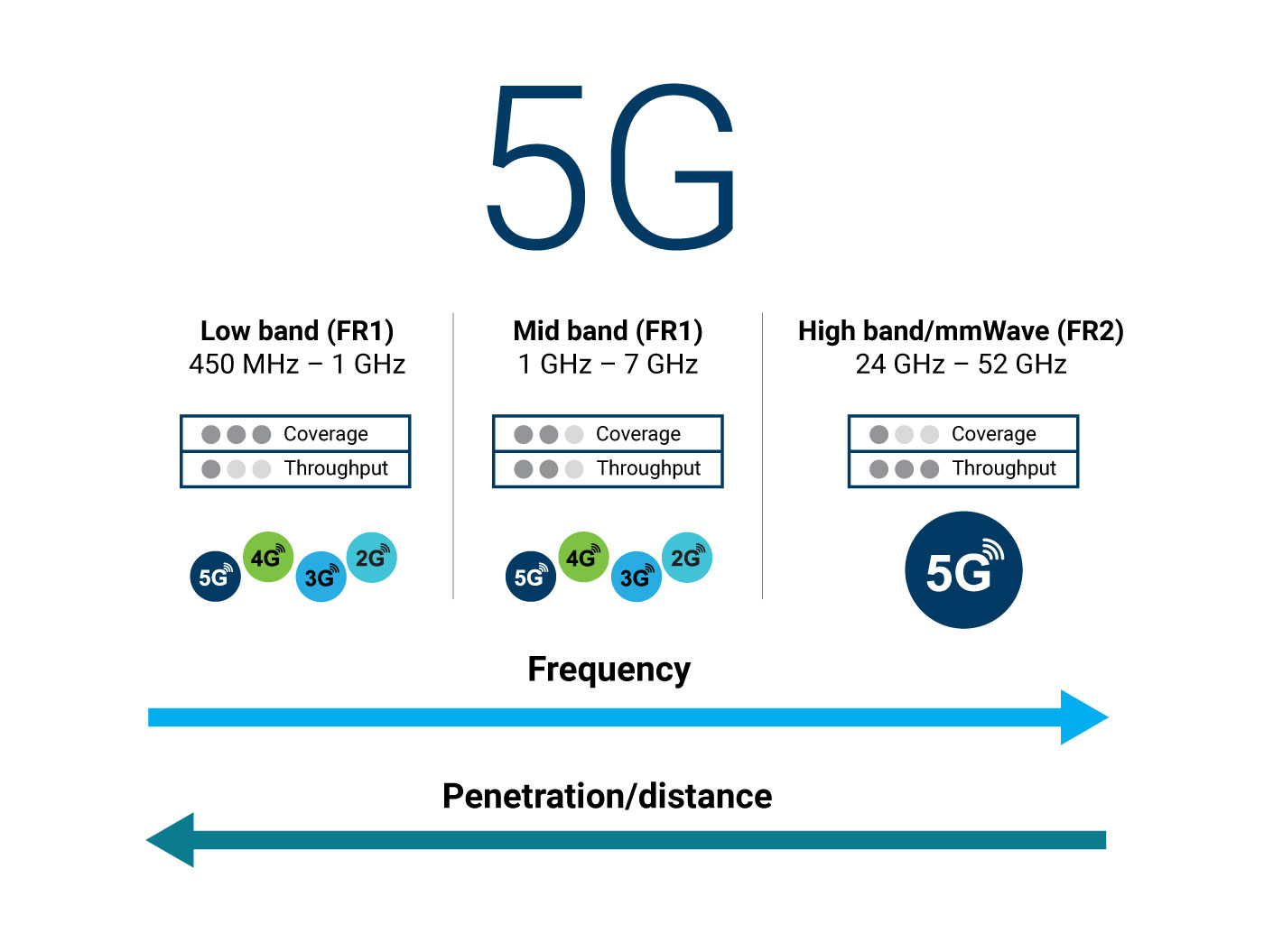
Coverage is usually the other key parameter for wireless network technology. Increase in coverage is generally not seen as a fundamental technology challenge, but more a cost of deployment challenge. Sub 1 GHz networks give good coverage, and now 5G is adding satellite communications (Non-Terrestrial Networks) to provide more cost-effective coverage of hard-to-reach areas. But certainly, the interest in millimetre wave and terahertz technology for 6G is not driven by coverage requirements (quite the opposite really).

Defining channel capacity

The fundamental definition of “Channel Capacity” is laid out in Shannon’s equation, based on the ground breaking paper published in 1948 by Claude Shannon on the principles of information theory and error coding. This defines the theoretical maximum data capacity over a communications medium (a communications channel) in the presence of noise.

Where:

C = Channel Capacity.

B = Channel Bandwidth.

S/N = Signal to Noise Ratio of the received signal.

Clearly then the Channel Capacity is a function of the Channel Bandwidth and of the received Signal to Noise Ratio (SNR). But the important point to note in this equation is that the capacity is a linear function of the bandwidth, but a Logarithmic term of the SNR. We can see that a 10x increase in bandwidth will increase the capacity by 10x, but a 10x increase in SNR will only increase the capacity by 2x. This effect can be seen in figure 1 where we plot capacity versus the linear BW term and the logarithmic SNR term.From this we can quickly see that there appear to be more gains in channel capacity from using more bandwidth, rather than trying to improve SNR. However, there is still considerable interest in optimising the SNR term, so we can maximise the available channel capacity for any given bandwidth that is available for use.

This effect is seen clearly in the development and evolution of 5G networks, and even 4G networks. Much focus has been put into ‘Carrier Aggregation’ as this technique directly increases the channel bandwidth. Especially for the downlink, this requires relatively little increase in the UE performance (generally more processing is needed). There has been only small interest in using higher order modulation schemes such as 256 QAM or 1024 QAM, as the capacity gains are less and the required implementation into the UE is more expensive (higher performance transmitter and receiver is required).

Increasing the Channel Bandwidth term in 6G.

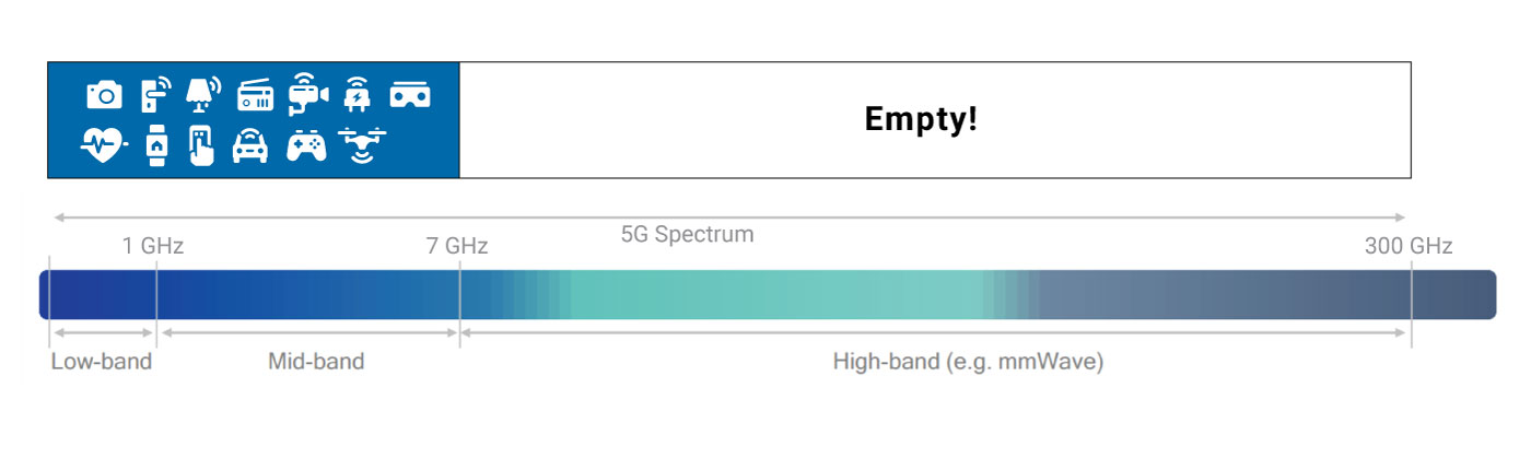
As shown in figure 1, the bandwidth term has a direct linear relationship to the channel capacity. So, network operators are wanting to use ‘new’ bandwidth to expand capacity of their networks. Of course, the radio spectrum is crowded and there is only a limited amount of bandwidth available to be used. This search for new bandwidth was seen in the move to 3G (2100 MHz band), and to 4G (800 MHz, 2600 MHz, and re-farming of old 2G/3G bands), and then in 5G there was the move to the millimetre wave bands (24-29 GHz, 37-43 GHz).

As we are considering the absolute bandwidth (Hz) for the channel capacity, if we search to find 100 MHz of free spectrum to use then at 1 GHz band this is very demanding (10% of the available spectrum) whereas at 100 GHz this is relatively easier (0.1% of the available spectrum). Hence, as we move to higher operating frequency then it becomes increasingly easier to find new bandwidth, as the amount of bandwidth that exists is far wider and the chances to find potentially available bandwidth becomes much higher. However, as we move to higher frequencies then the physics of propagation starts to work against us.

As shown in figure 2, the pathloss of radiation from an isotropic antenna is increased by the square of the frequency (f2). We can see that a 10x increase if the operating frequency leads to a 100x increase in losses (20 dB losses) for an isotropic radiation source if the other related parameter of distance is kept constant. This type of loss is usually overcome by having a physically ‘large’ Rx antenna, so by keeping the physical size of the Rx antenna to the same size when we move to higher frequencies, then this loss can be mostly overcome. By using ‘large’ antennas, we have additional antenna gain due to the narrow beam directivity of the antennas, and this helps to overcome the propagation loses. However, this directivity introduces the need for alignment of Tx and Rx beams to complete a radio link, and the consequent alignment error between Tx and Rx beam that must be controlled.

Technology

The second type of loss we incur as we move to higher frequencies is the atmospheric attenuation loss. This occurs due to particles in the atmosphere that absorb, reflect, or scatter the radiated energy from the transmitter and so reduce the amount of signal that arrives at the receiver. This type of loss has a strong link between the wavelength (frequency) of the signal and the physical size of the particles in the atmosphere. So as we move to wavelengths of 1mm or less then moisture content (rain, cloud, fog, mist etc) and dust particles (e.g sand) can significantly increase attenuation. In addition, certain molecular structures (e.g. H2O, CO2, O2) have a resonance at specific wavelengths and this causes sharp increases in the attenuation at these resonant frequencies. If we look at the atmospheric attenuation as we move from 10GHz to 1 THz, we therefore see the gradual increase in attenuation caused by the absorption/scattering, and then we see additional peaks super-imposed that are caused by molecular resonances. In-between these resonant frequencies we can find “atmospheric windows” where propagation is relatively good, and these are seen at 35, 94, 140, 220 & 360 GHz regions.

Current 5G activity is including the window around 35 GHz (5G is looking at 37-43 GHz region), and the O2 absorption region at 65 GHz (to enable dense deployment of cells with little leakage of signal to neighbouring cells due to the very high atmospheric losses). Currently the windows around 94 GHz, 140 GHz, and 220 GHz are used for other purposes (e.g. satellite weather monitoring, military and imaging radars) and so studies for 6G are considering also operation up to the 360 GHz region. As we can see from figure 3, atmospheric losses in these regions are up to 10 times higher than existing 38GHz bands, leading to an extra pathloss of 10 dB per kilometre.

So far we have only considered the ‘real’ physical channel bandwidth. Starting in 3G, and then deployed widely in both 4G and 5G, is the technology called MIMO (Multiple Input Multiple Output). With this technology, we seek to increase the channel bandwidth by creating additional ‘virtual channels’ between transmitter and receiver. This done by having multiple antennas at the transmit side and multiple antennas at the receive side. ‘Spatial multiplexing’ MIMO uses baseband pre- coding of the signals to compensate for the subtle path differences between the sets of Tx and Rx antennas, and these subtle path differences enable separate channels to be created on the different Tx-Rx paths. A 2×2 MIMO system can create 2 orthogonal channels, and hence increase data rate by a factor of 2.

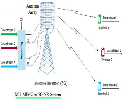
A further step is called ‘Massive MIMO’, where there are significantly more Tx antennas than there are Rx antennas. In this scenario then a single set of Tx antennas can create individual MIMO paths to multiple Rx sides (or vice versa) so that a single Massive MIMO base station may provide MIMO enhanced links to multiple devices simultaneously. This can significantly increase the capacity of the cell (although not increasing the data rate to a single user beyond the normal MIMO rate).

A practical limitation of MIMO is that the orthogonality of the spatial channels must be present, and then must be characterised (by measurements) and then compensated for in the channel coding algorithms (pre-coding matrices). As we move to higher order MIMO with many more channels to measure/code, and if we have more complex channel propagation characteristics at the THz bands, then the computational complexity of MIMO can become extremely high and the effective implementation can limit the MIMO performance gains. For 6G there is great interest in developing new algorithms that can use Artificial Intelligence (AI) and Machine Learning (ML) in the MIMO coding process, so that the computational power of AI/ML can be applied to give higher levels of capacity gain. This should enable more powerful processing to deliver higher MIMO gain in 6G and enable the effective use of MIMO at Terahertz frequencies.

A further proposal that is being considered for future 6G networks is the use of ‘Meta-materials’ to provide a managed/controlled reflection of signals. The channel propagation characteristic, and hence the MIMO capacity gains, are a function of the channel differences (orthogonality) and the ability to measure these differences. This channel characteristic is a function of any reflections that occur along a channel path. Using meta-materials we could actively control the reflections of signals, to create an ‘engineered’ channel path. These engineered channels could then be adjusted to provide optimal reflection of signal for a direct path between Tx and Rx, or to provide an enhanced ‘orthogonality’ to enable high gain MIMO coding to be effective.

The figure 4 shows the difference in a limited BW approach to a wide BW approach for achieving high data rates. The limited BW approach requires very high SNR and high modulation schemes (1024QAM) and high order MIMO (4×4), and even this combination of 1GHz + 1024QAM + 4×4 is not yet realisable in 5G. With the wider BW available in THz regions (e.g. 50GHz) then only a modest SNR level (QPSK) and no MIMO is required to reach much higher data rates. So the clear data rate improvement of wider BW can be easily seen.


Technology

Increasing the SNR term in 6G

The detailed operation of the SNR term, and the related modulation coding scheme (MCS), is shown in figure 5. As we increase the SNR in the channel, then it is possible to use a higher order MCS in the channel to enable a higher transmission rate. The use of error correction schemes (e.g. Forward Error Correction, FEC) was established as a means to achieve these theoretical limits when using a digital modulation scheme. As the SNR is reduced, then a particular MCS goes from ‘error free transmission’ to ‘channel limited transmission’ where Shannon’s equation determines the maximum data rate that an error correction process can sustain. This is seen in figure 5, where each MCS type goes from error free to the Shannon limited capacity. In reality, the capacity under channel limited conditions does not meet to the Shannon limit but different error correction schemes attempt to come closer to this theoretical limit (although error correction schemes can have a trade-off between processing power/speed required for the error correction versus the gains in channel capacity). Cellular networks such as 5G normally avoid the channel limited conditions and will switch between different MCS schemes (based on the available SNR) to aim on error free transmission where possible.

The yellow shaded zone, in-between the Shannon Limit line and the actual channel capacity of a specific MCS type, denotes the inefficiency or coding overhead of the Error Correction scheme.

The first aspect of improving the SNR term is to develop new coding schemes and error correction schemes (e.g. beyond current schemes such as Turbo, LDPC, Polar) which attempt to reduce this gap whilst using minimum processing power. This represents the first area of research, to gain improved channel capacity under noise limited conditions without requiring power hungry complex decoding algorithms. As the data rates are dramatically increased, the processing ‘overhead’, the cost/complexity, and the power consumption (battery drain) of implementing the coding scheme must all be kept low. So new coding schemes for more efficient implementation are very important for 6G, with practical implementations that can deliver the 100 Gbps rates being discussed for 6G.

To optimise the channel coding schemes requires more complex channel modelling to include effects of absorption and dispersion in the channel. With more accurate models to predict how the propagation channel affects the signal, then more optimised coding and error correction schemes can be used that are more efficiently matched to the types of errors that are likely to occur.

The second aspect of the SNR term is to improve the Signal level at the receiver (increase the Signal part of the SNR) by increasing the signal strength at the transmitter (increase transmit power, Tx). We normally have an upper limit for this Tx power which is set by health and safety limits (e.g. SAR limits, human exposure risks, or electronic interference issues). But from a technology implementation viewpoint, we also have limitations in available Tx power at millimetre wave and Terahertz frequencies, especially if device size/power consumption is limited. This is due to the relatively low Power Added Efficiency (PAE) of amplifier technology at these frequencies. When we attempt to drive the amplifiers to high power, we eventually reach a saturation limit where further input power does not correspond to useful levels of increased output power (the amplifier goes into saturation). At these saturated power levels, the signal is distorted (reducing range) and the power efficiency of the amplifier is reduced (increasing power consumption).

The chart in figure 6 shows a review of the available saturated (maximum) output power versus frequency for the different semiconductor materials used for electronic circuits. We can see that power output in the range +20 to +40 dBm is commercially available up to 100 GHz. At higher frequencies we can see that available power for traditional semiconductors quickly drops off to the range -10 to +10 dBm, representing a drop of around 30 dB in available output power. The results and trend for InP show promise to provide useful power out to the higher frequencies. Traditional ‘high power’ semiconductors such as GaAs and GaN show high power out to 150 GHz but have not shown commercial scale results yet for higher frequencies. The performance of the alternative technology of Travelling Wave Tubes (TWT) is also shown in figure 6, which provides a technology to generate sufficient power at the higher frequencies. However, the cost, size, power consumption of a TWT does not make it suitable for personal cellular communications today.

For higher frequencies (above 100 GHz) existing semiconductor materials have very low power efficiency (10% PAE for example). This means that generally we have low output powers achievable using conventional techniques, and heating issues as there is a high level (90%) of ‘wasted’ power to be dissipated. This leads to new fundamental research needed in semiconductor materials and compounds for higher efficiency, and new device packaging for lower losses and improved heat management. Transporting the signals within the integrated circuits and to the antenna with low loss also becomes a critical technology issue, as a large amount of power may be lost (turned into heat) from just the transportation of the signal power from the amplifier to the antenna. So, there is a key challenge in packaging of the integrated circuits without significant loss, and in maintaining proper heat dissipation.

In addition to the device/component level packaging discussed above, a commercial product also requires consumer packaging such that the final product can be easily handled by the end user. So, this requires that plastic/composite packaging materials that give sufficient scratch, moisture, dirt, and temperature protection to the internal circuits are available. Moving to the higher frequency bands above 100 GHz, then the properties of the materials must be verified to give low transmission loss and minimal impact on beam shape/forming circuits, so that the required SNR can be maintained.

Technology

Moving up to THz range frequency results in large increase in atmospheric path-loss, as discussed earlier in this paper. Very high element count (massive) antenna arrays are a solution to compensate for the path-loss by having higher power directional beams. Designing such arrays that will operate with high efficiency at THz frequency poses many challenges, from designing the feed network and the antenna elements to support GHz-wide bandwidth. The benefit is that an array of multiple transmitters can produce a high output power more easily than having a single high-power output. The challenge is then to focus the combined power of the individual antenna elements into a single beam towards the receiver.

So, we can use beamforming antenna arrays for higher gain (more antennas to give more Tx power arriving at a receiver) to overcome the atmospheric propagation losses and reduced output power. The use of massive arrays to create high antenna gain, and the higher frequency, results in very narrow beams. It is of great importance to optimize the beamforming methods to provide high dynamic-range and high flexibility at a reasonable cost and energy consumption, as beam forming of narrow and high gain beams will be very important. These higher frequency communication links will depend on ‘Line Of Sight’ and direct-reflected paths, not on scattering and diffracting paths, as the loss of signal strength due to diffraction or scattering is likely to make signal levels too low for detection. So, along with the beam forming there needs to be beam management that enables these narrow beams to be effectively aligned and maintained as the users move within the network. Current 5G beam management uses a system of Reference Signals and UE measurements/reports to track the beams and align to be the best beam. This method can incur significant overheads in channel capacity, and for 6G there needs to be research into more advanced techniques for beam management.

The third aspect of the SNR term is to improve the noise in the receiver (to lower the Noise part of the SNR).

The receiver noise becomes an important factor in the move to wider bandwidth (increasing the B term, as discussed above), as the wider bandwidth will increase the receiver noise floor. This can be seen as both the receiver noise power increasing, and also the ‘desired signal’ power density being decreased, as the same power (e.g. +30 dBm of Tx power) of desired signal is spread across a wider bandwidth. Both factors will serve to degrade the Signal to Noise Ratio. So improving the receiver noise power will directly improve the SNR of the received signal.

The receiver noise power is made up of the inherent thermal noise power, and the active device noise power (shot noise)

from semiconductor process. By improving the performance of the semiconductor material, then lower shot noise can be achieved. In addition, a third noise type, transit time noise, occurs in semiconductor materials when they are driven above a certain cut-off frequency (fc). So, there is also interest in improving the cut-off frequency of semiconductor materials to enable them to be used efficiently at the higher frequencies of 100-400 GHz region.

The thermal noise is given by the fundamental equation:

𝑃 = 𝑘𝑇𝐵

Where P is the noise Power, k is the Boltzman constant, and T is the temperature (ºKelvin). So, it is clearly seen that increasing the bandwidth term, B, directly increases the thermal noise power. This noise is independent of the semiconductor material, and assuming a ‘room temperature’ device (i.e. not with a specific ultra-low temperature cooling system) then this noise cannot be avoided and is just increased by having wider bandwidth. So, this represents a fundamental limitation which must be accounted for in any new system design.

OFDM (multi carrier) has challenges due to requirement for low phase noise, versus single carrier systems. This may limit the efficiency of OFDM systems in Terahertz bands, as current available device technology has relatively high phase noise. The phase noise component is normally due to the requirement to have a reference ‘local oscillator’ which provides a fixed reference frequency/phase against which the received signal is compared to extract the I&Q demodulation information.

The reference oscillator is usually built from a resonator circuit and a feedback circuit, to provide a stable high-quality reference. But any noise in the feedback circuit will generate noise in the resonator output, and hence create phase noise in the reference signal that then introduces corresponding phase noise into the demodulated signal. In the Local Oscillator signal of the transmitting and receiving system, the phase noise is increased by the square of the multiplication from the reference signal. Therefore, it is necessary to take measures such as cleaning the phase noise of the reference signal before multiplication.

In Terahertz bands, the phase noise may be solved by advances in device technology and signal processing. In addition, more efficient access schemes (beyond OFDMA) are being considered for 6G. OFDMA has a benefit of flexibility for different bandwidths, and a low cost and power efficient implementation into devices. This is important to ensure it can be deployed into devices that will be affordable and have acceptable battery life (talk time). Moving to very wide bandwidth systems in 6G and expecting higher spectral efficiency (more bits/sec/Hz), then alternative access schemes are being investigated and tested. The impact of phase noise onto the performance of candidate access schemes will need to be verified to ensure feasibility of implementing the access schemes.

Measurement challenges for wireless communications in Terahertz bands.

The move to higher frequency in THz band brings the same RF device technology challenges to the test equipment. The RF performance (e.g. noise floor, sensitivity, phase noise, spurious emissions) of test equipment needs to be ensured at a level that will give reliable measurements to the required uncertainty/accuracy.

As new semiconductor compounds and processes are developed, then the semiconductor wafers need to be characterised so that the device behaviour can be accurately fed into simulations and design tools. The accuracy and reliability of these measurements is essential for good design and modelling of device behaviour when designing terahertz band devices. The principal tool for this characterisation is a Vector Network Analyser (VNA), and new generation VNA’s are now able to characterise 70KHz – 220GHz in a single sweep, using advanced probes and probe station technology to connect to the test wafers. This ‘single sweep’ approach gives the very highest level of measurement confidence and is essential for the high quality characterisation needed for next generation of device design. Figure 7 shows a VNA system configured for ‘single sweep’ 70KHz-220GHz, being used to characterise semiconductor wafer samples on a probe station.TechnologyWider bandwidth signals require a wider bandwidth receiver to capture and analyse the signal, and this will have a higher receiver noise floor. This noise floor creates ‘residual EVM’ below which a measurement system cannot measure the EVM of a captured signal. For a 5G NR system (8 x 100 MHz) this is 0.89% EVM, but for a wider bandwidth system (e.g. 10 GHz) this could be 3.2% EVM. So careful attention must be paid to the required performance and measurements for verifying the quality wide bandwidth signals. When analysing a modulated carrier signal, the very wide bandwidth creates a very low power spectral density of the signal. If the power spectral density of the received signal is comparable to the power spectral density of the receiver noise, then accurate measurement will not be possible. The dynamic range and sensitivity of test equipment also becomes a challenge at very wide bandwidths. It is usually not possible to just increase the power level of the measured signal to overcome the receiver noise floor, as the ‘total power’ in the receiver may become excessive and cause saturation/non-linear effects in the receiver.

To overcome the possible performance limitations (e.g. dynamic range, conversion losses) then new architectures are being investigated to give optimal cost/performance in these higher frequency band and higher bandwidth test environments.

This work includes finding new Spectrum Analyser technology, and broadband VNA architectures, to enable fundamental device characterisation. An example of a 300GHz Spectrum measurement system using a new ‘pre-selector’ technology is shown in figure 8.

Technology

Radio transmitters and receivers often use frequency multipliers as converters to generate very high frequency signals from a stable reference of a low frequency. One challenge with this method is that any phase noise in the reference frequency is also multiplied by the square of the frequency multiplication factor, which can lead to high noise signals which degrade performance. In a receiver, there may also be a Sub-harmonic mixers to easily down-convert a high frequency into a more manageable lower frequency, but these sub-harmonic mixers give many undesired frequency response windows (images). Both effects represent significant challenges for test equipment, as the tester needs to have very high performance (to measure the signals of interest) and flexibility of configuration to be able to measure a wide range of devices. So new technologies, devices, and architectures to overcome these implementation challenges are being investigated for the realisation of high-performance test equipment. An example of this is the use of photonics and opto-electronic components for implementing a high frequency oscillator with low phase noise and high power, where two laser diode sources are mixed together and a resulting IF frequency is generated in the terahertz band.

During early stages of a new radio access method or new frequency band, then characterisation of the modulation/coding type and the frequency band propagation is a key research activity. This characterisation is used to help develop and verify models for coding and error correction schemes. To support this, often a “Channel Sounding” solution is used to make measurements on the frequency channel and for waveform evaluation. This channel sounder is normally composed of a complex (vector) signal source and vector signal analyser. This enables both the phase and amplitude of the channel response to be measured. Such vector transmission systems can be built from either separate Vector Signal Generator and Vector Signal Analyser, or from a combined Vector Network Analyser. This will require Vector Signal Generators and Vector Signal Analysers capable of operating up into the 300 GHz bands. Figure 9 shows a 300GHz band signal generator and spectrum analyser being used in a laboratory evaluation system.TechnologyWith the expected use of AI/ML in many algorithms that control the radio link (e.g. schedulers for Modulation and Coding Scheme, or MIMO pre-coding), then the ability of a network emulator to implement and reproduce these AI/ML based algorithms may become critical for characterising device performance. Currently in 3GPP these algorithm areas are not standardised and not part of the testing scope, but this is likely to change as AI/ML becomes more fundamental to the operation of the network. So, the test equipment may need the ability to implement/reproduce the AI/ML based behaviour.

The move to millimetre wave (24-43 GHz) in 5G has already introduced many new challenges for ‘Over The Air’ OTA measurements. OTA is required as the antenna and Tx/Rx circuits become integrated together to provide the required low loss transceiver performance. But this integration of antenna and Tx/Rx means that there is no longer an RF test port to make RF measurements, and instead all the measurements must be made through the antenna interface. OTA measurement brings challenges in terms of equipment size (large chambers are required to isolate the test device from external signals), measurement uncertainty (the coupling through the air between test equipment and device is less repeatable), and measurement time (often the measurement must be repeated at many different incident angles to the antenna). When moving to THz band frequencies the chamber size may be reduced, but the measurement uncertainties become more demanding due to the noise floor and power limitations discussed above. So careful attention is now being paid to OTA measurement methods and uncertainties, so that test environments suitable for 6G and THz bands can be implemented.

Summary

The expected requirements for higher data rates (and higher data capacity) in a wireless cell are part of the key drivers for beyond 5G and 6G technology research. These requirements can be met with either a wider channel bandwidth (B), or an improved channel Signal to Noise Ratio (SNR). It is seen from Shannon’s equation that increasing B gives a greater return than increasing SNR, although both are relevant and of interest.

Due to the heavy use of existing frequency bands, there is a strong interest to use higher frequencies to enable more bandwidth. This is generating the interest to move to beyond 100 GHz carrier frequencies and to the Terahertz domain, where higher bandwidths (e.g. 10 GHz or more of bandwidth) can be found and could become available for commercial communications systems. The reason that these bands have not previously been used for commercial wireless systems is mainly due to propagation limits (high attenuation of signals) and cost/complexity/efficiency of semiconductor technology to implement circuits at these higher frequencies.

This requirement, and existing technology/implementation restrictions, is now driving research into the use of higher frequency bands (e.g. in the region of 100-400 GHz) and research activities in the following key topic areas:

  • Channel sounding and propagation measurements, to characterise and model the propagation of wireless transmission links and to evaluate candidate access schemes such as
  • Advanced MIMO systems, to additional channel capacity by using multiple spatial
  • Error coding schemes to improve efficiency and approach closer to Shannon limits of SNR
  • Advanced beamforming and reflector surfaces (meta-surfaces) to enable narrow beam signals to be used for high gain directional
  • Device and semiconductor technology to give lower shot noise and high fc, and lower phase noise
  • Semiconductor and packaging technology to give lower loss transmit modules, higher power efficiency and high output power, at the higher frequency
  • Technology and packaging for integrated antenna systems suitable for both Cell Site and User equipment

In general, it is seen that there are many implementation challenges in using the frequency range 100-400 GHz. For frequencies below 100 GHz then existing RF semiconductor devices can implement the technology with acceptable size/cost/efficiency. Above 10 THz then there are optical device technologies which can also implement the required functions in an acceptable way. Currently there is this ‘Terahertz gap’, spanning the range 100 GHz to 10 THz, where the cross-over between optical/photonics and RF/electronics technologies occurs and where the new device implementation technology is being developed for commercial solutions.

In parallel, the use of AI/ML is being investigated to enhance the performance of algorithms that are used in many of the communications systems functions. This includes the areas of channel coding and error correction, MIMO, beamforming, and resource scheduling.

All the above technology themes and challenges are now being investigated by research teams and projects across the world. The results will deliver analysis and proposals into the standards making processes and Standards Developing Organisations (SDO’s) such as 3GPP, to enable the selection of technologies and waveforms for the Beyond 5G and 6G networks. Not only the theoretical capability, but the practical implications and available technology for affordable and suitable commercial solutions, are critical points for the selection of technology to be included in the standards for next generation cellular communications systems.

The importance of interoperability testing for O-RAN validation

6 Apr
Being ‘locked in’ to a proprietary RAN has put mobile network operators (MNOs) at the mercy of network equipment manufacturers.

Throughout most of cellular communications history, radio access networks (RANs) have been dominated by proprietary network equipment from the same vendor or group of vendors. While closed, single-vendor RANs may have offered some advantages as the wireless communications industry evolved, this time has long since passed. Being “locked in” to a proprietary RAN has put mobile network operators (MNOs) at the mercy of network equipment manufacturers and become a bottleneck to innovation.

Eventually, the rise of software-defined networking (SDN) and network function virtualization (NFV) brought to the network core greater agility and improved cost efficiencies. But the RAN, meanwhile, remained a single-vendor system.

In recent years, global MNOs have pushed the adoption of an open RAN (also known as O-RAN) architecture for 5G. The adoption of open RAN architecture offers a ton of benefits but does impose additional technical complexities and testing requirements.

This article examines the advantages of implementing an open RAN architecture for 5G. It also discusses the principles of the open RAN movement, the structural components of an open RAN architecture, and the importance of conducting both conformance and interoperability testing for open RAN components.

The case for open RAN

The momentum of open RAN has been so forceful that it can be challenging to track all the players, much less who is doing what.

The O-RAN Alliance — an organization made up of more than 25 MNOs and nearly 200 contributing organizations from across the wireless landscape — has since its founding in 2018 been developing open, intelligent, virtualized, and interoperable RAN specifications. The Telecom Infra Project (TIP) — a separate coalition with hundreds of members from across the infrastructure equipment landscape ­—maintains an OpenRAN project group to define and build 2G, 3G, and 4G RAN solutions based on general-purpose hardware-neutral hardware and software-defined technology. Earlier this year, TIP also launched the Open RAN Policy Coalition, a separate group under the TIP umbrella focused on promoting policies to accelerate and spur adoption innovation of open RAN technology.

Figure 1. The major components of the 4G LTE RAN versus the O-RAN for 5G. Source: Keysight Technologies

In February, the O-RAN Alliance and TIP announced a cooperative agreement to align on the development of interoperable open RAN technology, including the sharing of information, referencing specifications, and conducting joint testing and integration efforts.

The O-RAN Alliance has defined an O-RAN architecture for 5G and has defined a 5G RAN architecture that breaks down the RAN into several sections. Open, interoperable standards define the interfaces between these sections, enabling mobile network operators, for the first time, to mix and match RAN components from several different vendors. The O-RAN Alliance has already created more than 30 specifications, many of them defining interfaces.

Interoperable interfaces are a core principle of open RAN.  Interoperable interfaces allow smaller vendors to quickly introduce their own services. They also enable MNOs to adopt multi-vendor deployments and to customize their networks to suit their own unique needs. MNOs will be free to choose the products and technologies that they want to utilize in their networks, regardless of the vendor. As a result, MNOs will have the opportunity to build more robust and cost-effective networks leveraging innovation from multiple sources.

Enabling smaller vendors to introduce services quickly will also improve cost efficiency by creating a more competitive supplier ecosystem for MNOs, reducing the cost of 5G network deployments. Operators locked into a proprietary RAN have limited negotiating power. Open RANs level the playing field, stimulating marketplace competition, and bringing costs down.

Innovation is another significant benefit of open RAN. The move to open interfaces spurs innovation, letting smaller, more nimble competitors develop and deploy breakthrough technology. Not only does this create the potential for more innovation, it also increases the speed of breakthrough technology development, since smaller companies tend to move faster than larger ones.

Figure 2. Test equipment radio in the O-RAN conformance specification.

Other benefits of open RAN from an operator perspective may be less obvious, but no less significant. One notable example is in the fronthaul — the transport network of a Cloud-RAN (C-RAN) architecture that links the remote radio heads (RRHs) at the cell sites with the baseband units (BBUs) aggregated as centralized baseband controllers some distance (potentially several miles) away. In the O-RAN Alliance reference architecture, the IEEE Radio over Ethernet (RoE) and the open enhanced CPRI (eCPRI) protocols can be used on top of the O-RAN fronthaul specification interface in place of the bandwidth-intensive and proprietary common public radio interface (CPRI). Using Ethernet enables operators to employ virtualization, with fronthaul traffic switching between physical nodes using off-the-shelf networking equipment. Virtualized network elements allow more customization.

Figure 1 shows the layers of the radio protocol stack and the major architectural components of a 4G LTE RAN and a 5G open RAN. Because of the total bandwidth required and fewer antennas involved, the CPRI data rate between the BBU and RRH was sufficient for LTE. With 5G,  higher data rates and the increase in the number of antennas due to massive multiple-input / multiple-output (MIMO) means passing a lot more data back and forth over the interface. Also, note that the major components of the LTE RAN, the BBU and the RRH, are replaced in the O-RAN architecture by O-RAN central unit (O-CU), the O-RAN distributed unit (O-DU), and the O-RAN radio unit (O-RU), all of which are discussed in greater detail below.

The principles and major components of an open RAN architecture

As stated earlier (and implied by the name), one core principle of the open RAN architecture is openness — specifically in the form of open, interoperable interfaces that enable MNOs to build RANs that feature technology from multiple vendors. The O-RAN Alliance is also committed to incorporating open source technologies where appropriate and maximizing the use of common-off-the-shelf hardware and merchant silicon while minimizing the use of proprietary hardware.

A second core principle of open RAN, as described by the O-RAN Alliance, is the incorporation of greater intelligence. The growing complexity of networks necessitates the incorporation of artificial intelligence (AI) and deep learning to create self-driving networks. By embedding AI in the RAN architecture, MNOs can increasingly automate network functions and minimize operational costs. AI also helps MNOs increase the efficiency of networks through dynamic resource allocation, traffic steering, and virtualization.

The three major components of the O-RAN for 5G (and retroactively for LTE) are the O-CU, O-DU, and the O-RU.

  • The O-CU is responsible for the packet data convergence protocol (PDCP) layer of the protocol.
  • The O-DU is responsible for all baseband processing, scheduling, radio link control (RLC), medium access control (MAC), and the upper part of the physical layer (PHY).
  • The O-RU is the component responsible for the lower part of the physical layer processing, including the analog components of the radio transmitter and receiver.

Two of these components can be virtualized. The O-CU is the component of the RAN that is always centralized and virtualized. The O-DU is typically a virtualized component; however, virtualization of the O-DU requires some hardware acceleration assistance in the form of FPGAs or GPUs.

At this point, the prospects for virtualization of the O-RU are remote. But one O-RAN Alliance working group is planning a white box radio implementation using off-the-shelf components. The white box enables the construction of an O-RU without proprietary technology or components.

Interoperability testing required

While the move to open RAN offers numerous benefits for MNOs, making it work means adopting rigorous testing requirements. A few years ago, it was sufficient to simply test an Evolved Node B (eNB) as a complete unit in accordance with 3GPP requirements. But the introduction of the open RAN and distributed RANs change the equation, requiring testing each component of the RAN in isolation for conformance to the standards and testing combinations of components for interoperability.

Why test for both conformance and interoperability? In the O-RAN era, it is essential to determine both that the components conform to the appropriate standards in isolation and that they work together as a unit. Skipping the conformance testing step and performing only interoperability testing would be like an aircraft manufacturer building a plane from untested parts and then only checking to see if it flies.

Conformance testing usually comes first to ensure that all the components meet the interface specifications. Testing each component in isolation calls for test equipment that emulates the surrounding network to ensure that the component conforms to all capabilities of the interface protocols.

Conformance testing of components in isolation offers several benefits. For one thing, conformance testing enables the conduction of negative testing to check the component’s response to invalid inputs, something that is not possible in interoperability testing. In conformance testing, the test equipment can stress the components to the limits of their stated capabilities — another capability not available with interoperability testing alone. Conformance testing also enables test engineers to exercise protocol features that they have no control over during interoperability testing.

The conformance test specification developed by the O-RAN Alliance open fronthaul interfaces working group features several sections with many test categories to test nearly all 5G O-RAN elements.

Interoperability testing of a 5G O-RAN is like interoperability testing of a 4G RAN. Just as 4G interoperability testing amounts to testing the components of an eNB as a unit, the same procedures apply to testing a gNodeB (gNB) in 5G interoperability testing. The change in testing methodology is minimal.

Conformance testing, however, is significantly different for 5G O-RAN and requires a broader set of equipment. For example, the conformance test setup for an O-RU includes a vector signal analyzer, a signal source, and an O-DU emulator, plus a test sequencer for automating the hundreds of tests included in a conformance test suite. Figure 2 shows the test equipment radio in the O-RAN conformance test specification.

Conclusion: Tools and Methodologies Matter

As we have seen, the open RAN movement has considerable momentum and is a reality in the era of 5G. while the adoption of open RAN architecture brings significant benefits in terms of greater efficiency, lower costs, and an increase in innovation. However, the test and validation of a multi-vendor open RAN is no small endeavor. Simply cobbling together a few instruments and running a few tests is not an adequate solution. Testing each section individually to the maximum of its capabilities is critical.

Choosing and implementing the right equipment for your network requires proper testing with the right tools, methodologies, and strategies.

Source: https://www.ept.ca/features/the-importance-of-interoperability-testing-for-o-ran-validation/ 06 04 21

RF and 5G new radio: top 5 questions answered

29 Mar

1. Which RF frequency bands are used by 5G and how does that compare to 4G?

The goal of 5G technologies extends farther than just serving mobile broadband and offers key advancements that enable a much wider range of applications. Additional 5G frequency bands are being made available to support these applications (see Figure 1). 5G NR includes several low and mid-frequency bands in the sub-7 GHz range, defined as FR1, as well as higher frequency bands above 24 GHz, defined as FR2/mmWave. 5G frequency includes all previous cellular spectrum and additional spectrum in the sub-7 GHz frequency range and beyond. A key reason that additional spectrum is being made available is to address the overcrowding in sub-7 GHz bands (see Figure 1)—and to overcome the physical limitations associated with throughput and bandwidth. For example, 4G bands accounted for up to 20 MHz of bandwidth whereas 5G bands now allow up to 400 MHz of bandwidth per channel.

Figure 1. Frequency spectrum bands and bandwidth availability.

2. What challenges come along with mmWave?

The term millimeter wave (mmWave) refers to a specific part of radio frequency (RF) spectrum with very short wavelengths (i.e., from 24.25 GHz to 52.6 GHz, as specified by 5G 3GPP). The use of mmWave will greatly increase the amount of 5G bandwidth available since this spectrum was mostly unused until now. Another advantage of mmWave is that it can transfer data even faster, even though its transfer distance is shorter. Plus, mmWave bands are less crowded. In contrast, lower frequencies are more heavily congested with TV and radio signals, as well as with current 4G LTE network signals which typically sit between 700 MHz and 3,000 MHz.

However, mmWave spectrum requires strict line-of-sight between user equipment (UE) and radio antennas. Any obstacle, or passive obstruction like highway signs in front of cell sites, trees or buildings as well as moving objects such as cars, have the potential to degrade or block a 5G FR2 signal (see Figure 2).

Figure 2. 5G radio frequency spectrum.

3. How does massive MIMO (mMIMO) and beamforming reduce 5G signal degradation?

Multiple input, multiple output (MIMO) is a technology deployed throughout legacy 4G/LTE networks whereby radio transmitters are equipped with multiple antenna ports that enable multiple data streams to be transmitted simultaneously to user equipment. MIMO is used to double (2×2 MIMO) or quadruple (4×4 MIMO) throughput performance for users connected to a cell site.

Massive MIMO (mMIMO) is an extension of MIMO, increasing the number of antennas to a 64-transmit/64-receive (64T64R MIMO) configuration. This results in mobile cell sites with higher throughput and improved efficiency.

Beamforming is a subset of mMIMO and as these new technologies come into play, we often see some confusion between the two terms. Beamforming is a signal processing technique that uses the multiple antennas available with mMIMO to create a focused signal (or beam) between an antenna and specific user equipment (see Figure 3). Signals can be controlled by modifying the magnitude and phase giving the ability for the antenna to focus on specific users. This concept can be compared to a music concert where a spotlight is focused on specific performers onstage.

This advanced RF technology is key for 5G and especially for mmWAVE bands because it solves the line-of-sight problem by steering signals around objects and can even bounce signals against building walls in order to reach user equipment.

Figure 3. Beamforming signal processing technique

4. Why are 5G mid-bands key to accelerating 5G deployments?

5G can be a challenging technology to deploy, however mid-band spectrum in the 1 GHz – 7 GHz frequency range is considered ideal for 5G as it strikes the perfect balance between coverage and throughput. The 5G community finds the 3.3 GHz to 3.8 GHz mid-bands especially appealing because this will enable most countries to have a dedicated 5G band in the sub-7 GHz range.

In the United States, RF spectrum bands ranging from 3.5 GHz to 3.7 GHz are referred to as Citizens Broadband Radio Service (CBRS). The Federal Communications Commission (FCC) in the United States has designated that this CBRS spectrum be managed by the CBRS Alliance and shared among three tiers of users: incumbent access users, priority access licenses (PALs) and generally authorized access (GAA) users. Incumbent users include military and fixed satellite stations. PALs include operators who must acquire their spectrum block through spectrum auction (licensed spectrum). The GAA tier is comprised of unlicensed spectrum available for use by anyone, free of charge.

New 5G radio equipment enables Massive MIMO (mMIMO) and beamforming at 3.5 GHz. Initially, beamforming was available only within higher mmWAVE bands. Now radio equipment vendors are enabling beamforming for 5G mid-bands as well, making those bands more appealing. These new 5G mid-bands simplify rollouts and accelerate the race to 5G. Around the world, spectrum auctions are being held to acquire these new bands and mobile operators that want to take the lead in 5G deployments will need deep pockets in order to win these coveted 5G mid-bands.

5. What is TDD and why is it important for 5G?

Time Division Duplexing (TDD) is a technique to emulate full-duplex communication over a half-duplex communication link by transmitting the downlink (DL) and receiving the uplink (UL) at the same frequency but using synchronized time intervals (see Figure 4). The UL and DL are separated by a guard period to avoid overlapping of the communication channels. Due to advanced technology, the switching is done within milliseconds and therefore fast enough for low latency 5G scenarios. The advantage of this technique is that it excels in spectral efficiency and can deliver improved latency results.

Figure 4. Differences between FDD, TDD and TDD full duplex.

With 5G, technologies are quickly evolving. Engineers are pushing the boundaries of RF by using a single frequency and offering a true full-duplex communication, which means both the uplink and downlink operate at the same frequency and at the same time. To achieve 5G full-duplex on the same frequency, 5G NR uses a procedure called “echo-canceling” where end-customers transmit and receive signals simultaneously without any echo or self-interference. With voice calls, the transmitted signal is cancelled directly on each receiver enabling two people to speak at the same time without any overlap.


AIMM Leverages Reconfigurable Intelligent Surfaces Alongside Machine Learning

1 Dec
AIMM

Reconfigurable Intelligent Surfaces (RIS) goes by several names as an emerging technology. According to Marco Di Renzo, CNRS Research Director at CentraleSupélec of Paris-Saclay University, it is also known as Intelligent Reflecting Surfaces (IRS), Large Intelligent Surfaces (LIS), and Holographic MIMO. However it is referred to though, it’s a key factor in an ambitious collaborative project entitled AI-enabled Massive MIMO (AIMM), on which Di Renzo is about to start work.

Early Stages of RIS Research

Di Renzo refers to “RIS,” as does the recently established Emerging Technology Initiative of the Institute of Electrical and Electronics Engineers (IEEE). Furthermore, Samsung used that same acronym in its recent 6G Vision whitepaper, calling it a means “to provide a propagation path where no [line of sight] exists.” The description is arguably fitting considering there is no clear line of sight in the field, with a lot still to be discovered.

The intelligent surfaces, as the name suggests, possess reconfigurable reflection, refraction, and absorption properties with regard to electromagnetic waves. “We are doing a lot of fundamental research. The idea is really to push the limits and the main idea is to look at future networks,” Di Renzo said.

The project itself is two years in length, slated to conclude in September 2022. It’s also large in scale, featuring a dozen partners including InterDigital and BT, the former of which is steering the project. Arman Shojaeifard, Staff Engineer at InterDigital, serves as AIMM Project Lead. According to Shojaeifard, the “MIMO” in the name is just as much a nod to Holographic MIMO (or RIS) as it is to Massive MIMO.

“We are developing technologies for both in AIMM: Massive MIMO, which comprises sector antennas with many transmitters and receivers, and RIS, utilising reconfigurable reflect arrays for Holographic MIMO radios and smart wireless environments,” he explained.

Whereas reflective surfaces have generally been around for a while to passively improve coverage indoors, RIS is a recent development, with NTT Docomo demonstrating the first 28GHz 5G meta-structure reflect array in 2018. Compared to passive reflective surfaces, RIS also has many other potential use cases.

Slide courtesy of Marco Di Renzo, CentraleSupélec

“Two main applications of metasurfaces as reconfigurable reflect arrays are considered in AIMM,” said Shojaeifard. “One is to create smart wireless environments by placing the reflective surface between the base station and terminals to help existing antenna system deployments. And two is to realise low-complexity and energy-efficient Holographic MIMO. This could be a terminal or even a base station.”

Optimising the Operation through Machine Learning

The primarily European project includes clusters of companies in Canada, the UK, Germany, and France. In France specifically there are three partners: Nokia Bell Labs; Montimage, a developer of tools to test and monitor networks; and Di Renzo’s CentraleSupélec, for which he serves as Principal Investigator. Whereas Nokia is contributing to the machine-learning-based air interface of the project, Di Renzo is working on the RIS component.

“From a technological point of view, the idea is that you have many antennas in Massive MIMO, but behind each of them there is a lot of complexity, such as baseband digital signal processing units, RF chains, and power amplifiers,” he said. “What we want to do with [RIS] is to try to get the same benefits or close to the same benefits as Massive MIMO, as much as we can, but […] get the complexity, power consumption, and cost as low as we can.”

The need for machine learning is two-pronged, according to Di Renzo. It helps resolve a current deficiency regarding the analytical complexity of accurately modeling the electromagnetic properties of the surfaces. It also helps to optimise the surfaces when they’re densely deployed in large-scale wireless networks through the use of algorithms.

“[RIS] can transform today’s wireless networks with only active nodes into a new hybrid network with active and passive components working together in an intelligent way to achieve sustainable capacity growth with low cost and power consumption,” he said.

Ready, AIMM…

According to Shojaeifard, the AIMM consortium is targeting efficiency dividends and service differentiation through AI in 5G and Beyond-5G Radio Access Networks. He said InterDigital’s work here is closely aligned with its partnerships with University of Southampton and Finland’s 6G Flagship research group.

Meanwhile, Di Renzo believes the findings to be made can provide the interconnectivity and reliability required for applications such as those in industrial environments. As for the use of RIS in telecoms networks, it’s a possibility at the very least.

“I can really tell you that this is the moment where we figure out whether [RIS] is going to be part of the use of the telecommunications standards or not,” he said. “During the summer, many initiatives were created within IEEE concerning [RIS] and a couple of years ago for machine learning applied to communications.”

“We will see what is going to happen in one year or a couple of years, which is the time horizon of this project…This project AIMM really comes at the right moment on the two issues that are really relevant, the technology which is [RIS] and the algorithmic component which is machine learning […] It’s the right moment to get started on this project.”

Source: https://www.6gworld.com/exclusives/aimm-leverages-reconfigurable-intelligent-surfaces-alongside-machine-learning/ 01 12 20

6G does not exist, yet it is already here

7 Oct
The Average Revenue per User, ARPU, in LATAM -as in any other areas, has kept declining, in spite of an increase in network use -data transfer- and an increase in network performances. Image credit: Global Market Intelligence, 2019

I had, recently, an interesting conversation with some analysts looking at the implication of 6G. That in itself was surprising since most of the time analysts are looking at the next quarter. Yet, they were interested on what kind of impact 6G might have on telecom operators, telecom manufacturers and on the semiconductor industry. Of course, looking that far down the lane they were also interested in understanding what type of services might require a 6G.

I started the conversation saying that 6G does not exist, but then I said that it was already here, in terms of “prodrome”. In other words, looking at the past evolution and at the present situation it may be possible to detect a few signs that can be used to make some prediction on 6G. Since this is more a crystal ball exercise than applied science, I would appreciate very much your thoughts in this matter

Lessons from “G” evolution

If you look back, starting from 1G, each subsequent “G”, up to the 4th one was the result on the one hand of technology evolution and on the other of the need of Wireless Telecom Operators to meet a growing demand. Market was expanding (more users/cellphones) and more network equipment was needed. Having a new technology that could decrease the per-element cost (with respect to capacity) was a great incentive to move from one “G” to the next. Additionally, the expansion of the market resulted in an increase of revenues.

The CAPEX to pay for expanding the network (base stations and antennas sites mostly) could be recovered in a relatively short time thanks to an expanding market (not an expanding ARPU, the Average Revenue per User was actually decreasing). Additionally, the OPEX was also decreasing (again measured against capacity).

The expanding market meant more handsets sold with increasing production volumes leading to decreased price. More than that, The expanding market fuelled innovation in the handsets, with new models stimulating the top buyers to get a new one and attracting new buyers with lower cost models. All in all a virtual spiral that as increased sales increased the attractiveness of the wireless services (the me too effect).

It is in this “ensemble” that we can find the reason for the 10 years generation cycle. After ten years a new G arrives on the market. New tech is supporting it and economic reasons make the equipment manufacturers (network and device) and telecom operators ride (and push) the wave.

How is it that an exponential technology evolution does not result in an exponential acceleration of the demise of a previous G in favour of the next one? Why are the ten years basically stable?

There are a few reasons why:

  • The exponential technology evolution does not result in an exponential market adoption
  • The market perception of “novelty” is logarithmic (you need something that is 10 times more performant to perceive at 2 times better), hence the logarithmic perception combined with an exponential evolution leads to a linear adoption
  • New technology flanks existing one (we still have 2G around as 5G is starting to be deployed)

With the advent of 4G the landscape has changed. In many Countries the market has saturated, the space for expansion has dwindled and there is only replacement. Also, the coverage provided by the network has reached in most places 100% (or at least 100% of the area that is of interest to users). A new generation will necessarily cover a smaller surface expanding over time. Hence the market (that is each of us) wil stick to the previous generation since it is available everywhere. This has the nasty (for the Operators) implication that the new generation is rarely so appealing to sustain a premium price.

The price of wireless services has declined everywhere in the last twenty years. The graphic shows the decline in the US over the llast ten years. Image credit: Bureau of LLabor Statistics

An Operator will need to invest money to deploy the new “G” but its revenues will not increase. Why would then an Operator do that? Well, because it has no choice. The new generation has better performance and lower OPEX. If an Operator does not deploy the new “G” someone else will, attracting customers and running the network at lower cost, thus becoming able to offer lower prices that will undercut others’ Operators’ offer.

5G is a clear example of this new situation and there is no reason to believe that 6G may be any different. Actually, the more capacity (performance) is available with a given G (and 4G provides plenty to most users in most situations) the less the market is willing to pay a premium for the new G. By 2030 5G will be fully deployed and people will get capcity and performance that will exceed their (wildest) needs.
Having a 6G providing 100 Gbps vs a 1 Gbps of the 5G  is unlikely to find a huge number of customers willing to pay a premium. What is likely to happen is that the “cost” of the new network will have to be “paid” by services, not by connectivity. This opens up a quite different scenario.

The Shannon theorem, expanded, to take into account the use of several antennas. In the graphic W stands for the spectrum band, B in the original Shannon theorem, and SNR for the Signal Noise ratio. Image credit: Waveform

Spectrum efficiency

Over the last 40 years, since the very first analogue wireless systems, researchers have managed to increase the spectral efficiency, that is to pack more and more information in the radio waves. Actually, with the 4G they have reached the Shannon limit. Shannon (and Hartley) found a relation between the signal power and the noise on a channel that was limiting the capacity of that channel. Over that limit the errors will be such that the signal will no longer be useful (you can no longer distinguish the signal from the noise):

C=Blog(1+S/N)

where C is the theoretically available channel capacity (in bit/s), B is the spectrum band in Hz, S is the Signal power in W and N is the Noise power in W).

Since the spectral efficiency is a function of the signal power you cannot give an absolute number to it, by increasing the signal power you could overcome noise, hence pack more bit per Hz. In practice you have some limit to the power, dictated by the regulation (max V per meter allowed), the kind of average noise  in the transmission channel (very very low for optical fibre, much much higher from wireless in a urban area, even higher in a factory…) as well as to the use of battery power.

Today, in normal usage condition and with the best wireless system, the Shannon limit for wireless system is around 4 bit per Hz (that is for every available Hz in the spectrum range allocated to that wireless transmission you can squeeze in 4 bits. Notice that because of the complexity of the environment condition you can find numbers from 0.5 to 13 in spectral efficiency, what I am indicating is a “compromise” just to give an idea of where we are). A plain 3G system may have a 1 bit per Hz in spectral efficiency, a plain vanilla 4G reaches 2.5 and with QAM 64 reaches 4.

This limit has already been overcome using “tricks” like higher order modulation (like QAM 256 reaching 6.3 bit per Hz) and most importantly using MIMO, Multiple Input Multiple Output.

This latter is really a nice way to circumvent the Shannon limit. This limit is about the use of a single channel. Of course, if you use more channels you can increase the number of bits per Hz, as long as these channels do not interfere with one another. This is actually the key point! By using several antennas, in theory, I could create many channels. one for each antenna couple (transmitting and receiving). However these parallel transmission (using the same frequency and spectrum band) will be interfering with one another.

Here comes the nice thing: “interference” does not exist! Interference is not a property of waves. Waves do not interfere. If a wave meets another wave, it does not stop to shake hands, rather each one continues undisturbed and unaffected on its way. What really happens is that an observer will no longer be able to distinguish one wave from the other at the point where they meet/overlap. So, the interference is a problem in the detector, not of the waves. You can easily visualise this as you look at a calm sea. You will notice small waves and in some areas completely flat patches. These are areas where waves meet and overlap annihilating one another (a crest of one adds to the trough of the other resulting in a flat area). If you have “n” transmitting antennas and “n+1” receiving antennas (each separated from the others at least half-wavelength, then you can sort out the interference and get the signal. This is basically the principle of MIMO. To exploit it you need sufficient processing power to manage all signals received in parallel by the antennas and this is something I will address in a future post. For now it is good to know that there is a way to circumvent the Shannon limit and expand the capacity of a wireless system.

6G will not just exploit massive MIMO, it will be able to do something amazing: spread the signal processing across many devices, each one acting as an array of antennas. Rather than having a single access point in 6G, in theory at least, you can have an unlimited number of access points, thus multiplying the overall capacity. It would be like sending mails to many receivers. You may have a bottleneck in one point but the messages will get to other points that in turn will be able to relay them to the intended receiver once this is available.

Source: https://cmte.ieee.org/futuredirections/2020/10/07/6g-does-not-exist-yet-it-is-already-here-ii/ 07 10 20

A Vision of 6G Wireless Systems: Applications, Trends, Technologies, and Open Research Problems

9 Sep

ABSTRACT

The ongoing deployment of 5G cellular systems is continuously exposing the inherent limitations of this system, compared to its original premise as an enabler for Internet of Everything applications. These 5G drawbacks are currently spurring worldwide activities focused on defining the next-generation 6G wireless system that can truly integrate far-reaching applications ranging from autonomous systems to extended reality and haptics. Despite recent 6G initiatives One example is the 6Genesis project in Finland (see https://www.oulu.fi/6gflagship/)., the fundamental architectural and performance components of the system remain largely undefined. In this paper, we present a holistic, forward-looking vision that defines the tenets of a 6G system. We opine that 6G will not be a mere exploration of more spectrum at high-frequency bands, but it will rather be a convergence of upcoming technological trends driven by exciting, underlying services. In this regard, we first identify the primary drivers of 6G systems, in terms of applications and accompanying technological trends. Then, we propose a new set of service classes and expose their target 6G performance requirements. We then identify the enabling technologies for the introduced 6G services and outline a comprehensive research agenda that leverages those technologies. We conclude by providing concrete recommendations for the roadmap toward 6G. Ultimately, the intent of this article is to serve as a basis for stimulating more out-of-the-box research around 6G.

I – INTRODUCTION

To date, the wireless network evolution was primarily driven by an incessant need for higher data rates, which mandated a continuous 1000x increase in the network capacity. While this demand for wireless capacity will continue to grow, the emergence of the Internet of Everything (IoE) system, connecting millions of people and billions of machines, is yielding a radical paradigm shift from the rate-centric enhanced mobile broadband (eMBB) services of yesteryears towards ultra-reliable, low latency communications (URLLC).

Although the fifth generation (5G) cellular system was marketed as the key IoE enabler, through concerted 5G standardization efforts that led to the first 5G new radio (5G NR) milestone (for non-standalone 5G) and subsequent 3GPP releases, the initial premise of 5G – as a true carrier of IoE services – is yet to be realized. One can argue that the evolutionary part of 5G (i.e., supporting rate-hungry eMBB services) has gained significant momentum, however, the promised revolutionary outlook of 5G – a system operating almost exclusively at millimeter wave (mmWave) frequencies and enabling heterogeneous IoE services – has thus far remained a mirage. Although the 5G systems that are currently being marketed will readily support basic IoE and URLLC services (e.g., factory automation), it is debatable whether they can deliver the tomorrow’s smart city IoE applications. Moreover, even though 5G will eventually support fixed-access at mmWave frequencies, it is more likely that early 5G roll-outs will be centered around sub-6 GHz, especially for supporting mobility.

Meanwhile, an unprecedented proliferation of new IoE services is ongoing. Examples range from eXtended reality (XR) services (encompassing augmented, mixed, and virtual reality (AR/MR/VR)) to telemedicine, haptics, flying vehicles, brain-computer interfaces, and connected autonomous systems. These applications will disrupt the original 5G goal of supporting short-packet, sensing-based URLLC services. To successfully operate IoE services such as XR and connected autonomous systems, a wireless system must simultaneously deliver high reliability, low latency, and high data rates, for heterogeneous devices, across uplink and downlink. Emerging IoE services will also require an end-to-end co-design of communication, control, and computing functionalities, which to date has been largely overlooked. To cater for this new breed of services, unique challenges must be addressed ranging from characterizing the fundamental rate-reliability-latency tradeoffs governing their performance to exploiting frequencies beyond sub-6 GHz and transforming wireless systems into a self-sustaining, intelligent network fabric which flexibly provisions and orchestrates communication-computing-control-localization-sensing resources tailored to the requisite IoE scenario.

To overcome these challenges and catalyze the deployment of new IoE services, a disruptive sixth generation (6G) wireless system, whose design is inherently tailored to the performance requirements of the aforementioned IoE applications and their accompanying technological trends, is needed. The drivers of 6G will be a confluence of past trends (e.g., densification, higher rates, and massive antennas) and of emerging trends that include new services and the recent revolution in wireless devices (e.g., smart wearables, implants, XR devices, etc.), artificial intelligence (AI), computing, sensing, and 3D environmental mapping.

 6G Vision: Applications, Trends, and Technologies.
Fig. 1: 6G Vision: Applications, Trends, and Technologies.

The main contribution of this article is a bold, forward-looking vision of 6G systems that identifies the applications, trends, performance metrics, and disruptive technologies, that will drive the 6G revolution. The proposed vision will then delineate new 6G services and provide a concrete research roadmap and recommendations to facilitate the leap from current 5G systems towards 6G.

II – 6G DRIVING APPLICATIONS, METRICS, AND NEW SERVICE CLASSES

Every new cellular system generation is driven by innovative applications. 6G is no exception: It will be borne out of an unparalleled emergence of exciting new applications and technological trends that will shape its performance targets while radically redefining standard 5G services. In this section, we first introduce the main applications that motivate 6G deployment and, then, discuss ensuing technological trends, target performance metrics, and new service requirements.

II-ADRIVING APPLICATIONS BEHIND 6G AND THEIR REQUIREMENTS

While traditional applications, such as live multimedia streaming, will remain central to 6G, the key determinants of the system performance will be four new application domains:

Multisensory XR Applications

XR will yield many killer applications for 6G across the AR/MR/VR spectrum. Upcoming 5G systems still fall short of providing a full immersive XR experience capturing all sensory inputs due to their inability to deliver very low latencies for data-rate intensive XR applications. A truly immersive AR/MR/VR experience requires a joint design integrating not only engineering (wireless, computing, storage) requirements but also perceptual requirements stemming from human senses, cognition, and physiology. Minimal and maximal perceptual requirements and limits must be factored into the engineering process (computing, processing, etc.). To do so, a new concept of quality-of-physical-experience (QoPE) measure is needed to merge physical factors from the human user itself with classical QoS (e.g., latency and rate) and QoE (e.g., mean-opinion score) inputs. Some factors that affect QoPE include brain cognition, body physiology, and gestures. As an example, we have shown that the human brain may not be able to distinguish between different latency measures, when operating in the URLLC regime. Meanwhile, we showed that visual and haptic perceptions are key for maximizing wireless resource utilization. Concisely, the requirements of XR services are a blend of traditional URLLC and eMBB with incorporated perceptual factors that 6G must support.

Connected Robotics and Autonomous Systems (CRAS)

A primary driver behind 6G systems is the imminent deployment of CRAS including drone-delivery systems, autonomous cars, autonomous drone swarms, vehicle platoons, and autonomous robotics. The introduction of CRAS over the cellular domain is not a simple case of “yet another short packet uplink IoE service”. Instead, CRAS mandate control system-driven latency requirements as well as the potential need for eMBB transmissions of high definition (HD) maps. The notion of QoPE applies once again for CRAS; however, the physical environment is now a control system, potentially augmented with AI. CRAS are perhaps a prime use case that requires stringent requirements across the rate-reliability-latency spectrum; a balance that is not yet available in 5G.

Wireless Brain-Computer Interactions (BCI)

Beyond XR, tailoring wireless systems to their human user is mandatory to support services with direct BCI. Traditionally, BCI applications were limited to healthcare scenarios in which humans can control prosthetic limbs or neighboring computing devices using brain implants. However, the recent advent of wireless brain-computer interfaces and implants will revolutionize this field and introduce new use-case scenarios that require 6G connectivity. Such scenarios range from enabling brain-controlled movie input to fully-fledged multi-brain-controlled cinema. Using wireless BCI technologies, instead of smartphones, people will interact with their environment and other people using discrete devices, some worn, some implanted, and some embedded in the world around them. This will allow individuals to control their environments through gestures and communicate with loved ones through haptic messages. Such empathic and haptic communications, coupled with related ideas such as affective computing in which emotion-driven devices can match their functions to their user’s mood, will constitute important 6G use cases. Wireless BCI services will require fundamentally different performance metrics compared to what 5G delivers. Similar to XR, wireless BCI services need high rates, ultra low latency, and high reliability. However, they are much more sensitive than XR to physical perceptions and will necessitate QoPE guarantees.

Blockchain and Distributed Ledger Technologies (DLT)

Blockchains and DLT will be one of the most disruptive IoE technologies. Blockchain and DLT applications can be viewed as the next-generation of distributed sensing services whose need for connectivity will require a synergistic mix of URLLC and massive machine type communications (mMTC) to guarantee low-latency, reliable connectivity, and scalability.

II-B6G: DRIVING TRENDS AND PERFORMANCE METRICS

The applications of Section II-A lead to new system-wide trends that will set the goals for 6G:

  • Trend 1 – More Bits, More spectrum, More Reliability: Most of the driving applications of 6G require higher bit rates than 5G. To cater for applications such as XR and BCI, 6G must deliver yet another 1000x increase in data rates yielding a target of around 1 Terabit/second. This motivates a need for more spectrum resources, hence motivating further exploration of frequencies beyond sub-6 GHz. Meanwhile, the need for higher reliability will be pervasive across most 6G applications and will be more challenging to meet at high frequencies.

  • Trend 2 – From Spatial to Volumetric Spectral and Energy Efficiency: 6G must deal with ground and aerial users, encompassing smartphones and XR/BCI devices along with flying vehicles. This 3D nature of 6G requires an evolution towards a volumetric rather than spatial bandwidth definition. We envision that 6G systems must deliver high spectral and energy efficiency (SEE) requirements measured in bps/Hz/m/Joules. This is a natural evolution that started from 2G (bps) to 3G (bps/Hz), then 4G (bps/Hz/m) to 5G (bps/Hz/m/Joules).

  • Trend 3 – Emergence of Smart Surfaces and Environments: Current and past cellular systems used base stations (of different sizes and forms) for transmission. We are currently witnessing a revolution in electromagnetically active surfaces (e.g., using metamaterials) that include man-made structures such as walls, roads, and even entire buildings, as exemplified by the Berkeley ewallpaper project. See https://bwrc.eecs.berkeley.edu/projects/5605/ewallpaper.. The use of such smart large intelligent surfaces and environments for wireless communications will drive the 6G architectural evolution.

  • Trend 4 – Massive Availability of Small Data: The data revolution will continue in the near future and shift from centralized, big data, towards massive, distributed “small” data. 6G systems must harness both big and small datasets across their infrastructure to enhance network functions and provide new services. This trend motivates new machine learning and data analytics techniques that go beyond classical big data.

  • Trend 5 – From Self-Organizing Networks (SON) to Self-Sustaining Networks: SON has only been scarcely integrated into 4G/5G networks due to a lack of real-world need. However, CRAS and DLT technologies motivate an immediate need for intelligent SON to manage network operations, resources, and optimization. 6G will require a paradigm shift from classical SON, whereby the network merely adapts its functions to specific environment states, into a self-sustaining network (SSN) that can maintain its key performance indicators (KPIs), in perpetuity, under highly dynamic and complex environments stemming from the rich 6G application domains. SSNs must be able to not only adapt their functions but to also sustain their resource usage and management (e.g., by harvesting energy and exploiting spectrum) to autonomously maintain high, long-term KPIs. SSN functions must leverage the recent revolution in AI technologies to create AI-powered 6G SSNs.

  • Trend 6 – Convergence of Communications, Computing, Control, Localization, and Sensing (3CLS): The past five generations of cellular systems had one exclusive function: wireless communications. However, the convergence of various technologies requires 6G to disrupt this premise by providing multiple functions that include communications, computing, control, localization, and sensing. We envision 6G as a multi-purpose system that can deliver multiple 3CLS services which are particularly appealing and even necessary for applications such as XR, CRAS, and DLT where tracking, control, localization, and computing are an inherent feature. Moreover, sensing services will enable 6G systems to provide users with a 3D mapping of the radio environment across different frequencies. Hence, 6G systems must tightly integrate and manage 3CLS functions.

  • Trend 7 – End of the Smartphone Era: Smartphones were central to 4G and 5G. However, recent years witnessed an increase in wearable devices whose functionalities are gradually replacing those of smartphones. This trend is further fueled by applications such as XR and BCI. The devices associated with those applications range from smart wearables to integrated headsets and smart body implants that can take direct sensory inputs from human senses; bringing an end to smartphones and potentially driving a majority of 6G use cases.

As shown in Table I, collectively, these trends impose new performance targets and requirements on next-generation wireless systems that will be met in two stages: a) A major beyond 5G evolution and b) A revolutionary step towards 6G.

5G Beyond 5G 6G
Application Types  eMBB.  Reliable eMBB. New applications (see Section II-C):
 URLLC.  URLLC.  MBRLLC.
 mMTC.  mMTC.  mURLLC.
 Hybrid (URLLC + eMBB).  HCS.
 MPS.
Device Types  Smartphones.  Smartphones.  Sensors and DLT devices.
 Sensors.  Sensors.  CRAS.
 Drones.  Drones.  XR and BCI equipment.
 XR equipment.  Smart implants.
Spectral and Energy Efficiency Gains with Respect to Today’s Networks 10x in bps/Hz/m 100x in bps/Hz/m 1000x in bps/Hz/m (volumetric)
Rate Requirements 1 Gbps 100 Gbps 1 Tbps
End-to-End Delay Requirements 5 ms 1 ms < 1 ms
Radio-Only Delay Requirements 100 ns 100 ns 10 ns
Processing Delay 100 ns 50 ns 10 ns
End-to-End Reliability Requirements Five 9s Six 9s Seven 9s
Frequency Bands  Sub-6 GHz.  Sub-6 GHz.  Sub-6 GHz.
 MmWave for fixed access.  MmWave for fixed access at 26 GHz and 28GHz.  MmWave for mobile access.
 Exploration of THz bands (above 140 GHz).
 Non-RF (e.g., optical, VLC, etc.).
Architecture  Dense sub-6 GHz small base stations with umbrella macro base stations.  Denser sub-6 GHz small cells with umbrella macro base stations.  Cell-free smart surfaces at high frequency supported by mmWave tiny cells for mobile and fixed access.
 < 100 m tiny and dense mmWave cells.
 MmWave small cells of about 100 m (for fixed access).  Temporary hotspots served by drone-carried base stations or tethered balloons.
 Trials of tiny THz cells.
TABLE I: Requirements of 5G vs. Beyond 5G vs. 6G.

II-CNEW 6G SERVICE CLASSES

Beyond imposing new performance metrics, the new technological trends will redefine 5G application types by morphing classical URLLC, eMBB, and mMTC and introducing new services (summarized in Table II), as follows:

Mobile Broadband Reliable Low Latency Communication

As evident from Section II-B, the distinction between eMBB and URLLC will no longer be sustainable to support applications such as XR, wireless BCI, or CRAS. This is because these applications require, not only high reliability and low latency but also high 5G-eMBB-level data rates. Hence, we propose a new service class called mobile broadband reliable low latency communication (MBRLLC) that allows 6G systems to deliver any required performance within the rate-reliability-latency space. As seen MBRLLC generalizes classical URLLC and eMBB services. Energy efficiency is central for MBRLLC, not only because of its impact on reliability and rate, but also because 6G devices will continue to shrink in size and increase in functionality.

MBRLLC services and several special cases (including classical eMBB and URLLC) within the rate-reliability-latency space. Other involved, associated metrics that are not shown include energy and network scale.
Fig. 2: MBRLLC services and several special cases (including classical eMBB and URLLC) within the rate-reliability-latency space. Other involved, associated metrics that are not shown include energy and network scale.

Massive URLLC

5G URLLC meant meeting reliability and latency of very specific uplink IoE applications such as smart factories,, for which prior work provided the needed fundamentals. However, 6G must scale classical URLLC across the device dimension thereby leading to a new massive URLLC (mURLLC) service that merges 5G URLLC with legacy mMTC. mURLLC brings forth a reliability-latency-scalability tradeoff which mandates a major departure from average-based network designs (e.g., average throughput/delay). Instead, a principled and scalable framework which accounts for delay, reliability, packet size, network architecture, topology (across access, edge, and core) and decision-making under uncertainty is necessary [1].

Human-Centric Services

We propose a new class of 6G services, dubbed human-centric services (HCS), that primarily require QoPE targets (tightly coupled with their human users, as explained in Section II-A) rather than raw rate-reliability-latency metrics. Wireless BCI are a prime example of HCS in which network performance is determined by the physiology of the human users and their actions. For such services, a whole new set of QoPE metrics must be defined and offered as function of raw QoS and QoE metrics.

Multi-Purpose 3CLS and Energy Services

6G systems must jointly deliver 3CLS services and their derivatives. They can also potentially offer energy to small devices via wireless energy transfer. Such multi-purpose 3CLS and energy services (MPS) will be particularly important for applications such as CRAS. MPS require joint uplink-downlink designs and must meet target performance for the control (e.g., stability), computing (e.g., computing latency), energy (e.g., target energy to transfer), localization (e.g., localization precision), as well as sensing and mapping functions (e.g., accuracy of a mapped radio environment).

Service Performance Indicators Example Applications
MBRLLC  Stringent rate-reliability-latency requirements.  XR/AR/VR.
 Energy efficiency.  Autonomous vehicular systems.
 Rate-reliability-latency in mobile environments.  Autonomous drones.
 Legacy eMBB and URLLC.
mURLLC  Ultra high reliability.  Classical Internet of Things.
 Massive connectivity.  User tracking.
 Massive reliability.  Blockchain and DLT.
 Scalable URLLC.  Massive sensing.
 Autonomous robotics.
HCS  QoPE capturing raw wireless metrics as well as human and physical factors.  BCI.
 Haptics.
 Empathic communication.
 Affective communication.
MPS  Control stability.  CRAS.
 Computing latency.  Telemedicine.
 Localization accuracy.  Environmental mapping and imaging.
 Sensing and mapping accuracy.  Some special cases of XR services.
 Latency and reliability for communications.
 Energy.
TABLE II: Summary of 6G service classes, their performance indicators, and example applications.

III – 6G: ENABLING TECHNOLOGIES

To enable the aforementioned services and guarantee their performance, a cohort of new, disruptive technologies must be integrated into 6G.

Above 6 GHz for 6G – from Small Cells to Tiny Cells

As per Trends 1 and 2, the need for higher data rates and SEE anywhere, anytime in 6G motivates exploring higher frequency bands beyond sub-6 GHz. As a first step, this includes further developing mmWave technologies to make mobile mmWave a reality in early 6G systems. As 6G progresses, exploiting frequencies beyond mmWave, at the terahertz (THz) band, will become necessary [14]. To exploit higher mmWave and THz frequencies, the size of the 6G cells must shrink from small cells to “tiny cells” whose radius is only a few tens meters. This motivates new architectural designs that need much denser deployments of tiny cells and new high-frequency mobility management techniques.

Transceivers with Integrated Frequency Bands

On their own, dense high-frequency tiny cells may not be able to provide the seamless connectivity required for mobile 6G services. Instead, an integrated system that can leverage multiple frequencies across the microwave/mmWave/THz spectra (e.g., using multi-mode base stations) is needed to provide seamless connectivity at both wide and local area levels.

Communication with Large Intelligent Surfaces

Massive MIMO will be integral to both 5G and 6G due to the need for better SEE, higher data rates, and higher frequencies (Trend 1). However, for 6G systems, as per Trend 3, we envision an initial leap from traditional massive MIMO towards large intelligent surfaces (LISs) and smart environments that can provide massive surfaces for wireless communications and for heterogeneous devices (Trend 7). LISs enable innovative ways for communication such as by using holographic radio frequency (RF) and holographic MIMO. LISs will likely play a basic role in early 6G roll-outs and become more central as 6G matures.

Edge AI

AI is witnessing an unprecedented interest from the wireless community driven by recent breakthroughs in deep learning, the increase in available data (Trend 4), and the rise of smart devices (Trend 7). Imminent 6G use cases for AI (particularly for reinforcement learning) revolve around creating SSNs (Trend 5) that can autonomously sustain high KPIs and manage resources, functions, and network control. AI will also enable 6G to automatically provide MPS to its users and to send and create 3D radio environment maps (Trend 6). These short-term AI-enabled 6G functions will be complemented by a so-called “collective network intelligence” in which network intelligence is pushed at the edge, running AI algorithms and machine learning on edge devices (Trend 7) to provide distributed autonomy. This new edge AI leap will create a 6G system that can integrate the services of Section II, realize 3CLS, and potentially replace classical frame structures.

Integrated Terrestrial, Airborne, and Satellite Networks

Beyond their inevitable role as users of 6G systems, drones can be leveraged to complement ground, terrestrial networks by providing connectivity to hotspots and to areas in which infrastructure is scarce. Meanwhile, both drones and terrestrial base stations may require satellite connectivity with low orbit satellites (LEO) and CubeSats to provide backhaul support and additional wide area coverage. Integrating terrestrial, airborne, and satellite networks and into a single wireless system will be essential for 6G.

Energy Transfer and Harvesting

6G could be the first generation of cellular systems that can provide energy, along with 3CLS (Trend 6). As wireless energy transfer is maturing, it is plausible to foresee 6G base stations providing basic power transfer for devices, particularly implants and sensors (Trend 7). Adjunct energy-centric ideas, such as energy harvesting (from RF or renewable sources) and backscatter will also be a component of 6G.

Beyond 6G

A handful of technologies will mature along the same time of 6G and, hence, potentially play a role towards the end of the 6G standardization and research process. One prominent example is quantum computing and communications that can provide security and long-distance networking. Currently, major research efforts are focused on the quantum realm and we expect them to intersect with 6G. Other similar beyond 6G technologies include integration of RF and non-RF links (including optical, neural, molecular, and other channels).

IV – 6G: RESEARCH AGENDA AND OPEN PROBLEMS

 Necessary foundations and associated analytical tools for 6G.
Fig. 3: Necessary foundations and associated analytical tools for 6G.

Building on the identified trends in Section II and the enabling technologies in Section III, we now put forward a research agenda for 6G along with selected open problems (summarized in Table III).

3D Rate-Reliability-Latency Fundamentals

Fundamental 3D performance of 6G systems, in terms of rate-reliability-latency tradeoffs and SEE is needed. Such analysis must quantify the spectrum, energy, and communication requirements that 6G needs to support the identified driving applications. Recent works provide a first step in this direction.

Exploring Integrated, Heterogeneous High-Frequency Bands

Exploiting mmWave and THz in 6G brings forth several new open problems from hardware to system design. For mmWave, supporting high mobility at mmWave frequencies will be a central open problem. Meanwhile, for THz, new transceiver architectures are needed along with new THz propagation models. High power, high sensitivity, and low noise figure are key transceiver features needed to overcome the very high path-loss at THz frequencies. Once these physical layer aspects are well-understood, developing new multiple access and networking paradigms under the highly varying and mobile mmWave and THz environments is necessary. Another important research direction is to study the co-existence of THz, mmWave, and microwave cells across all layers, building on early works such as.

3D Networking

Due to the integration of ground and airborne networks, as outlined in Section III, 6G must support communications in 3D space, including serving users in 3D and deploying 3D base stations (e.g., tethered balloons or temporary drones). This, in turn, requires concerted research on various fronts. First, measurement and (data-driven) modeling of the 3D propagation environment is needed. Second, new approaches for 3D frequency and network planning (e.g., where to deploy base stations, tethered balloons, or even drone-base stations) must be developed. Our work already showed that such 3D planning is substantially different from conventional 2D networks due to the new altitude dimension and the associated degrees of freedom. Finally, new network optimizations for mobility management, multiple access, routing, and resource management in 3D are needed.

Communication with LIS

As per Trend 3, 6G will provide wireless connectivity via smart LIS environments that include active frequency selective surfaces, metallic passive reflectors, passive/active reflect arrays, as well as nonreconfigurable and reconfigurable metasurfaces. Open research problems here range from the optimized deployment of passive reflectors and metasurfaces to AI-powered operation of reconfigurable LIS. Fundamental analysis to understand the performance of LIS and smart surfaces, in terms of rate, latency, reliability, and coverage is needed, building on the early works. Another important research direction is to investigate the potential of using LIS-based reflective surfaces to enhance the range and coverage of tiny cells and to dynamically modify the propagation environment. Using LIS for wireless energy transfer is also an interesting direction.

AI for Wireless

AI brings forward many major research directions for 6G. Beyond the need for massive, small data analytics as well as using machine learning (ML) and AI-based SSNs (realized using reinforcement learning and game theory), there is also a need to operate ML algorithms reliably over 6G to deliver the applications of Section II. To perform these critical application tasks, low-latency, high-reliability and scalable AI is needed, along with a reliable infrastructure. This joint design of ML and wireless networks is an important area of research for 6G.

QoPE Metrics

The design of QoPE metrics that integrate physical factors from human physiology (for HCS services) or from a control system (for CRAS) is an important 6G research area, especially in light of new, emerging devices (Trend 7). This requires both real-world psychophysics experiments as well as new, rigorous mathematical expressions for QoPE that combine QoS, QoE, and human perceptions. Theoretical development of QoPE can be achieved using techniques from other disciplines such as operations research (e.g., multi-attribute utility theory and machine learning. 6G will be the first generation to enable a new breed of applications (wireless BCI) leveraging multiple human cognitive senses.

Joint Communication and Control

6G needs to pervasively support CRAS. The performance of CRAS is governed by real-world control systems whose operation requires data input from wireless 6G links. Therefore, operating CRAS over 6G systems requires a communication and control co-design, whereby the performance of the 6G wireless links is optimized to cater for the stability of the control system and vice versa. Due to the traditional radio-centric focus (3GPP and IEEE fora), such a co-design has been overlooked in 5G. Meanwhile, prior works on networked control abstract the specifics of the wireless network and cannot apply to cellular communications. This makes the communication-control co-design a key research topic in 6G.

3cls

The idea of joint communication and control must be extended to the joint design of the entire 3CLS functions. The interdependence between computing, communication, control, localization, sensing, energy, and mapping has not yet been fully explored in an end-to-end manner. Key questions range from how to jointly meet the performance of all 3CLS services to multi-modal sensor fusion for reconstructing 3D images and navigating in unknown environments for navigating robots, autonomous driving, etc. 3CLS is needed for various applications including CRAS, XR, and DLT.

RF and non-RF Link Integration

6G will witness a convergence of RF and non-RF links that encompass optical, visible light communication (VLC), molecular communication, and neuro-communication, among others. Design of such joint RF/non-RF systems is an open research area.

Holographic Radio

RF holography (including holographic MIMO) and spatial spectral holography can be made possible with 6G due to the use of LIS and similar structures. Holographic RF allows for control of the entire physical space and the full closed loop of the electromagnetic field through spatial spectral holography and spatial wave field synthesis. This greatly improves spectrum efficiency and network capacity, and helps the integration of imaging and wireless communication. How to realize holographic radio is a widely open area.

An overview on the necessary analytical tools and fundamentals related to these open research problems is shown in Fig. 3.

Research Area Challenges Open Problems
3D Rate-Reliability-Latency Fundamentals  Fundamental communication limits.  3D performance analysis of rate-reliability-latency region.
 3D nature of 6G systems.  Characterization of achievable rate-reliability-latency targets.
 3D SEE characterization.
 Characterization of energy and spectrum needs for rate-reliability-latency targets.
Exploring Integrated, Heterogeneous High-Frequency Bands  Challenges of operation in highly mobile systems.  Effective mobility management for mmWave and THz systems.
 Susceptibility to blockage.  Cross-band physical, link, and network layer optimization.
 Short range.  Coverage and range improvement.
 Lack of propagation models.  Design of mmWave and THz tiny cells.
 Need for high fidelity hardware.  Design of new high fidelity hardware for THz.
 Co-existence of frequency bands.  Propagation measurements and modeling across mmWave and THz bands.
3D Networking  Presence of users and base stations in 3D.  3D propagation modeling.
 High mobility.  3D performance metrics.
 3D mobility management and network optimization.
Communication with LIS  Complex nature of LIS surfaces.  Optimal deployment and location of LIS surfaces.
 Lack of existing performance models.  LIS reflectors vs. LIS base stations.
 Lack of propagation models.  LIS for energy transfer.
 Heterogeneity of 6G devices and services.  AI-enabled LIS.
 Ability of LIS to provide different functions (reflectors, base stations, etc.).  LIS across 6G services.
 Fundamental performance analysis of LIS transmitters and reflectors at various frequencies.
AI for Wireless  Design of low-complexity AI solutions.  Reinforcement learning for SON.
 Massive, small data.  Big and small data analytics.
 AI-powered network management.
 Edge AI over wireless systems.
New QoPE Metrics  Incorporate raw metrics with human perceptions.  Theoretical development of QoPE metrics.
 Accurate modeling of human perceptions and physiology.  Empirical QoPE characterization.
 Real psychophysics experiments.
 Definition of realistic QoPE targets and measures.
Joint Communication and Control  Integration of control and communication metrics.  Communication and control systems co-design.
 Handling dynamics and multiple time scales.  Control-enabled wireless metrics.
 Wireless-enabled control metrics.
 Joint optimization for CRAS.
3CLS  Integration of multiple functions.  Design of 3CLS metrics.
 Lack of prior models.  Joint 3CLS optimization.
 AI-enabled 3CLS.
 Energy efficient 3CLS.
RF and non-RF Link Integration  Different physical nature of RF/non-RF interfaces.  Design of joint RF/non-RF hardware.
 System-level analysis of joint RF/non-RF systems.
 Use of RF/non-RF systems for various 6G services.
Holographic Radio  Lack of existing models.  Design of holographic MIMO using LIS.
 Hardware and physical layer challenges.  Performance analysis of holographic RF.
 3CLS over holographic radio.
 Network optimization with holographic radio.
TABLE III: Summary of Research Areas

V – CONCLUSION AND RECOMMENDATIONS

This article laid out a bold new vision for 6G systems that outlines the trends, challenges and associated research. While many topics will come as a natural 5G evolution, new avenues of research such as LIS-communication, 3CLS, holographic radio, and others will create an exciting research agenda for the next decade. To conclude, several recommendations are in order:

  • Recommendation 1: A first step towards 6G is to enable MBRLLC and mobility management at high-frequency mmWave bands and beyond (i.e., THz).

  • Recommendation 2: 6G requires a move from radio-centric system design (à-la-3GPP) towards an end-to-end co-design 3CLS under the orchestration of an AI-driven intelligence substrate.

  • Recommendation 3: The 6G vision will not be a simple case of exploring additional, high-frequency spectrum bands to provide more capacity. Instead, it will be driven by a diverse portfolio of applications, technologies, and techniques (see Figs. 1 and 3).

  • Recommendation 4: 6G will transition from the smartphone-base station paradigm into a new era of smart surfaces communicating with human-embedded implants.

  • Recommendation 5: Performance analysis and optimization of 6G requires operating in 3D space and moving away from simple averaging towards fine-grained analysis that deals with tails, distributions, and QoPE.

    Source: https://www.arxiv-vanity.com/papers/1902.10265/ 09 09 2020

Non-coherent Massive MIMO for High-Mobility Communications

7 Jul

While driving on a highway in Europe (as a passenger), I tried my smartphone’s 4G-LTE connection and the best I got was 30 Mbps downlink, 10 Mbps uplink, with latency around 50 msec. This is not bad for many of the applications we use today, but it is clearly insufficient for many low latency/low jitter mobile applications such as autonomous driving or high-quality video while on the move.

At higher speeds, passengers of ultra-fast trains may enjoy the travel while working. Their 4G-LTE connections are often good enough to read or send emails and browse the internet. But would a train passenger be able to have a video conference call with good quality? Would we ever be able to experience virtual reality or augmented reality in such a high mobility environment?

How to achieve intelligent transport systems enabling vehicles to communicate with each other has been the subject of several papers and reports. Many telecommunications professionals are looking to 5G for a solution, but it is not at all certain that the IMT 2020 performance requirements specified in ITU-R M.2410 for low latency with high speed mobility will be met anytime soon (by either 3GPP Release 16 or IMT 2020 compliant specifications).  

Editor’s Note: In ITU-R M.2410, the minimum requirements for user plane latency are: 4 ms for eMBB and 1 ms for URLLC.

The fundamental reason why we do not experience high data rates using 4G-LTE lies in the signal format. That did not change much with 3GPP’s “5G NR,” which is the leading candidate IMT 2020 Radio Interface Technology (RIT).

In coherent detection, a local carrier mixes with the received radio frequency (RF) signal to generate a product term. As a result, the received RF signal can be frequency translated and demodulated. When using coherent detection, we need to estimate the channel (frequency band). The amount of overhead strongly depends on the channel variations. That is, the faster we are moving, the higher the overhead. Therefore, the only way to obtain higher data rates in these circumstances is to increase the allocated bandwidth (e.g. with carrier aggregation for a particular connection, which is obviously a non-scalable solution.

Coherent Communications, CSI, and OFDM Explained:

A coherent receiver creates a replica of the transmitted carrier, as perfectly synchronized (using the same frequency and the same phase) as possible. Combining coherent detection with the received signal, the baseband data is recovered with additive noise being the only impairment.

However, the propagation channel usually introduces some additional negative effects that distorts the amplitude and phase of the received signal (when compared to the transmitted signal)Hence, the need to estimate the channel characteristics and remove the total distortion. In wireless communications, channel state information (CSI) refers to known channel properties of a communication link, i.e. the channel characteristics. CSI needs to be estimated at the receiver and is usually quantized and sent back to the transmitter.

Orthogonal frequency-division multiplexing (OFDM) is a method of digital signal modulation in which a single data stream is split across several separate narrowband channels at different frequencies to reduce interference and crosstalk. Modern communications systems using OFDM carefully design reference signals to be able to estimate the CSI as accurately as possible. That requires pilot signals in the composite Physical layer frame (in addition to the digital information being transmitted) in order to estimate the CSI. The frequency of those reference signals and the corresponding amount of overhead depends on the characteristics of the channel that we would like to estimate from some (hopefully) reduced number of samples.

Wireless communications were not always based on coherent detection. At the time of the initial amplitude modulation (AM) and frequency modulation (FM), the receivers obtained an estimate of the transmitted data by detecting the amplitude or frequency variations of the received signal without creating a local replica of the carrier. But their performance was very limited. Indeed, coherent receivers were a break-through to achieve high quality communications.

Other Methods of Signal Detection:

More recently, there are two popular ways of non-coherently detecting the transmitted data correctly at the receiver.

  1. One way is to perform energy or frequency detection in a similar way to the initial AM and FM receivers.

  2. In differential encoding, we encode the information in the phase shifts (or phase differences) of the transmitted carrier. Then, the absolute phase is not important, but just its transitions from one symbol to the other. The differential receivers are much simpler than the coherent ones, but their performance is worse since noise is increased in the detection process.

Communications systems that prioritize simple and inexpensive receivers, such as Bluetooth, use non-coherent receivers. Also, differential encoding is an added feature in some standards, such as Digital Audio Broadcasting (DAB). The latter was one of the first, if not the first standard, to use OFDM in wireless communicationsIt increases the robustness to mitigate phase distortions, caused by the propagation channel for mobile, portable or fixed receivers.

However, the vast majority of contemporary wireless communications systems use coherent detection. That is true for 4G-LTE and “5G NR.”

Combining non-coherent communications with massive MIMO:

Massive MIMO (multiple-input, multiple-output) groups together antennas at the transmitter and receiver to provide better throughput and better spectrum efficiency. When massive MIMO is used, obtaining and sharing CSI threatened to become a bottleneck, because of the large number of channels that need to be estimated because there are a very large number of antennas.

A Universidad Carlos III de Madrid research group started looking at a combination of massive MIMO with non-coherent receivers as a possible solution for good quality (user experience) high speed mobile communications. It is an interesting combination. The improvement of performance brought by the excess of antennas may counteract the fundamental performance loss of non-coherent schemes (usually 3 dB signal-to-noise ratio loss).

Indeed, our research showed that if we take into account the overhead caused by CSI estimation in coherent schemes, we have shown several cases in which non-coherent massive MIMO performs better than its coherent counterpart. There are even cases where coherent schemes do not work at all, at least with the overheads considered by 4G-LTE and 5G (IMT 2020) standards. Yet non-coherent detection usually works well under those conditions. These latter cases are most prevalent in high-mobility environments.

Editor’s Note:  In ITU-R M.2410, high speed vehicular communications (120 km/hr to 500 km/hr) is mainly envisioned for high speed trains.  No “dead zones” are permitted as the “minimum” mobility interruption time is 0 ms!

When to use non-coherent massive MIMO?

Clearly in those situations where coherent schemes work well with a reasonable pilot signal overhead, we do not need to search for alternatives. However, there are other scenarios of interest where non-coherent schemes may substitute or complement the coherent ones. These are cases when the propagation channel is very frequency selective and/or very time-varying. In these situations, estimating the CSI is very costly in terms of resources that need to be used as pilots for the estimation. Alternatives that do not require channel estimation are often more efficient.

An interesting combination of non-coherent and coherent data streams is presented in reference, where the non-coherent stream is used at the same time to transmit data and to estimate the CSI for the coherent stream. This is an example of how coherent and non-coherent approaches are complementary and the best combination can be chosen depending on the scenario. Such a hybrid scheme is depicted in the figure below.

Figure 1. Suitability of coherent (C), non-coherent (NC) and hybrid schemes (from reference [5])

………………………………………………………………………………………………………………………………………………………………………

What about Millimeter Waves and Beam Steering?

The advantage of millimeter waves (very high frequencies) is the spectrum availability and high speedsThe disadvantages are short distances and line of sight communications required.

Compensating for the overhead by adding more bandwidth, may be a viable solution. However, the high propagation loss that characterizes these millimeter wave high frequency bands creates the need for highly directive antennasSuch antennas would need to create narrow beams and then steer them towards the user’s position. This is easy when the user equipment is fixed or slowly moving, but doing it in a high speed environment is a real challenge.

Note that the beam searching and tracking systems that are proposed in today’s wireless communications standards, won’t work in high speed mobile communications when the User Endpoint (UE) has moved to the coverage of another base station at the time the steering beams are aligned! There is certainly a lot of research to be done here.

In summary, the combination of non-coherent techniques with massive MIMO does not present any additional problems when they are carried out in millimeter wave frequencies. For example how a non-coherent scheme can be combined with beamforming, provided the beamforming is performed by a beam tracking procedure. However, the problem of how to achieve fast beam alignment remains to be solved.

Concluding Remarks:

Non-coherent massive MIMO makes sense in wireless communications systems that need to have very low complexity or that need to work in scenarios with high mobility. Its advantage is that it makes possible communications in places or circumstances where the classical coherent communications fail. However, this scheme will not perform as well as coherent schemes under normal conditions.

Most probably, non-coherent massive MIMO will be used in the future as a complement to well-understood and (usually) well-performing coherent systems. This will happen when there are clear market opportunities for high mobility, high speed, low latency use cases and applications.

Source: https://techblog.comsoc.org/author/aweissberger/ 07 07 20

SU-MIMO vs MU-MIMO | Difference between SU-MIMO and MU-MIMO

13 Jun

This page compares SU-MIMO vs MU-MIMO and mentions difference between SU-MIMO and MU-MIMO with respect to 802.11ax (wifi6), 4G/LTE and 5G NR (New Radio) technologies.

Introduction : MIMO refers to multiple input multiple output. It basically refers to system having more than one antenna elements used either to increase system capacity, throughput or coverage. Beamforming techniques are used to concentrate radiated energy towards target UE which reduces interference to other UE’s and thereby improves the coverage.

There are two major types of MIMO with respect how the BS (Base Station) transmission is utilized by the mobile or fixed users. They are SU-MIMO and MU-MIMO. Both the types are used in the downlink direction i.e. from Base Station or eNB or Access point towards users.

There is another concept called massive MIMO or mMIMO in which combines multiple radio units and antenna elements on single active antenna unit. It houses 16/32/64/96 antenne elements. The massive MIMO employs beamforming which directs energy in desired user direction which reduces interference from undesired users.

SU-MIMO

• In SU-MIMO, all the streams of antenna arrays are focused on single user.
• Hence it is referred as Single User MIMO.
• It splits the available SINR between different multiple data layers towards target UE simultaneously where each layer is separately beamformed. This increases peak user throughput and system capacity.
• Here cell communicates with single user.
• Advantages : No interference

SU-MIMO vs MU-MIMO

The figure depicts SU-MIMO and MU-MIMO concept in IEEE 802.11ax (wifi6) system. It shows wifi6 compliant AP (Access Point) and wifi6 stations or users or clients.

MU-MIMO

• In MU-MIMO, multiple streams are focused on multi users. Moreover each of these streams provide radiated energy to more than one users.
• Hence it is referred as Multi User MIMO.
• It shares available SINR between multiple data layers towards multiple UEs simultaneously where each layer is separately beamformed. This increases system capacity and user perceived throughput.
• Here cell communicates with multi users.
• Advantages : Multiplexing gain

MU-MIMO in 5G NR

The figure depicts MU-MIMO used in mMIMO system in 5G. As shown multiple data streams (of multiple users) are passed through layer mapping/precoding before they are being mapped to antenna array elements and transmitted over the air.

Tabular difference between SU-MIMO and MU-MIMO

Following table summarizes difference between SU-MIMO and MU-MIMO.

Features SU-MIMO MU-MIMO
Full Form Single User MIMO Multi User MIMO
Function It is the mechanism in which information of single user is transmitted simultaneously over more than one data stream by BS (Base Station) in same time/frequency grid (i.e. resources). In MU-MIMO, data streams are distributed across multiple users on same time/frequency resources but dependent upon spatial separation.
Major Objective It helps in increasing user/link data rate as it is function of bandwidth and power availability. It helps in increasing system capacity i.e. number of users supported by base station.
Performance impact (Antenna Correlation) More susceptible Less susceptible
Performance Impact (Source of interference) Adjacent co-channel cells Links supporting same cell and other MU-MIMO users, and adjacent co-channel cells
Power allocation Split between multiple layers to same user. Fixed per transmit antenna Shared between multi-users and multiple layers. It can be allocated per MU-MIMO user based on channel condition.
CSI/Feedback process Varies upon implementation, TDD or FDD and reciprocity or feedback based. Less susceptible on feedback granularity and quality Very dependent upon CSI for channel estimation accuracy. More susceptible on feedback granularity and quality
Beamforming dependency Varies upon implementation TDD or FDD and reciprocity or feedback based. Less susceptible on feedback granularity and quality Greatly assisted by appropriate beamforming mechanisms (spatial focusing) which maximizes gain towards the intended users. More susceptible on feedback granularity and quality


WLAN 802.11ax related links

802.11n versus 802.11ax
802.11ac versus 802.11ax
Advantages and disadvantages of 802.11ax
BSS coloring in 11ax
RU in 802.11ax
MU-OFDMA in 802.11ax
MU-MIMO in 802.11ax
TWT power save mode in 802.11ax


5G NR Numerology | 5G NR Terminology


5G TECHNOLOGY RELATED LINKS

This 5G tutorial also covers following sub topics on the 5G technology:
5G basic tutorial    5G Frequency Bands    5G millimeter wave tutorial    5G mm wave frame    5G millimeter wave channel sounding    Difference between 4G and 5G    5G testing and test equipments    5G network architecture    5G network slicing    5G TF vs 5G NR    5G NR Physical layer    5G NR MAC layer    5G NR RLC layer    5G NR PDCP layer

What is Difference between

difference between 3G and 4G    difference between 4G and 5G    difference between 4.5G, 4.9G, 4G and 5G    difference between FDM and OFDM    Difference between SC-FDMA and OFDM    Difference between SISO and MIMO    Difference between TDD and FDD    Difference between 802.11 standards viz.11-a,11-b,11-g and 11-n    OFDM vs OFDMA    CDMA vs GSM    Bluetooth vs zigbee


Advantages and Disadvantages of other wireless technologies

IrDA    HomeRF    Bluetooth    Radar    RF    Wireless    Internet    Mobile Phone    IoT    Solar Energy    Fiber Optic    Microwave    Satellite    GPS    RFID    AM and FM    LTE


RF and Wireless Terminologies

Source: https://www.rfwireless-world.com/Terminology/Difference-between-SU-MIMO-and-MU-MIMO.html – 13 06 20