Archive | C-RAN RSS feed for this section

Rethinking of Optical Transport Network Design for 5G/6G Mobile Communication

20 Apr

Driven by the increasing use of emerging smart mobile applications, mobile technology is continuously and rapidly advancing towards the next generation communication systems such as 5G and 6G. However, the transport network, which needs to provide low latency and reliable connectivity between hundreds of thousands of cell sites and the network core, has not advanced at the same pace. This article provides insight into how we can solve the fundamental challenges of implementing cost-optimal transport and 5G and beyond mobile networks simultaneously while satisfying the network and user requirements irrespective of the radio access network’s architecture.

1. Introduction
The fifth generation (5G) mobile technology promises higher bandwidth capacities, lower latencies, and higher reliability for emerging time-sensitive and mission-critical applications [1]. According to Cisco, the number of connected devices will reach 500 billion by 2030, a number significantly higher than the expected world population. Providing connectivity for billions of devices and satisfying the stringent quality of service requirements of diverse applications is becoming a significant challenge. To address this ongoing issue, academia and industry recently started researching the sixth generation (6G) mobile technology [2].

6G mobile technology expects to provide 100 Gbps or higher data rates and ultra-low latency over ubiquitous 3D coverage areas. However, the transport network, which interconnects the cell sites with the network core, has not progressed at the same pace. For this reason, it has been identified as a potential bottleneck for high-performance and cost-efficient network deployment. Therefore, in order to fulfill the new and miscellaneous requirements of 5G and beyond mobile networks that are arising from the deployment of hundreds of thousands of wireless cell sites, increasingly diverse architectures, and sophisticated applications and services, “the transport network will require to undergo an evolutionary change with a complete rethink of the design and deployment strategies”.

In particular, optical technologies are positioned to be the most sustainable for the transport segment of 5G and beyond networks due to their inherent features such as secure data transmission and high capacity [3]. However, with the decreasing cell size and higher numbers of cells deployed, it becomes harder and more expensive to connect them to the network core with the optical network [4]. This is made even more challenging, given the diverse architectural requirements of radio access networks (RANs) of next-generation (xG) mobile networks [5]. Therefore, new methods are needed to jointly plan and design an xG RAN with its transport network while reducing the cost and meeting all the service requirements. In this article, we present new strategies that we can be applied to plan a 5G/6G network together with its optical transport infrastructure to provide ubiquitous, reliable, and cost-effective access for emerging applications.

2. Network Planning Strategies for 5G and Beyond
To support the unprecedented growth of mobile traffic, RAN has been undergoing diverse changes that directly impact the performance and cost of the network. Consequently, several RAN architectures have been proposed in the recent years. A future RAN may consist of multiple RAN architectures as shown in Fig. 1. The network architecture shown Fig.1 comprises multiple RAN architectures and their transport networks.

Optical Fig1
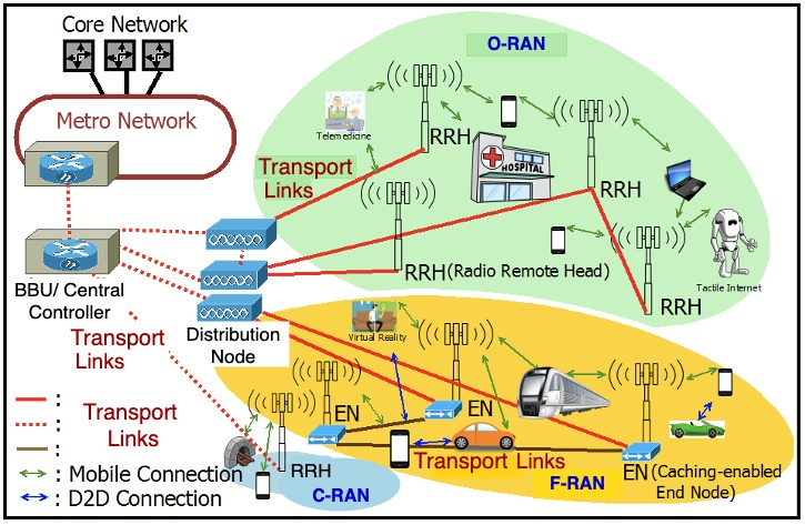
Figure 1. Radio Access Network Architectures for 5G and Beyond

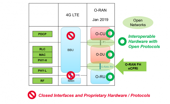
The centralized RAN (C-RAN) is one such paradigm in which the processing of mobile signals is carried out at the centralized base band unit (BBU) placed at the central office (CO). Consequently, in C-RAN, the remote radio heads (RRHs) placed at the cell sites have a very limited set of functions [6]. With the help of virtualization technology few other variants of C-RAN have been proposed and standardized including Open and Intelligent RAN (O-RAN) and fog RAN (F-RAN) [7,8]. In these RANs, the BBU can be further separated and radio control functions can be moved into the cloud, while the radio processing functions remain closer to the cell site, enabling functionalities like network slicing [7].

There is one thing in common irrespective of the RAN architecture in use, that is the requirement of reliable and cost-effective data transportation between RRH and CO. Each of these RAN architectures have different functions at BBU, the RRH and/or distribution node placed between the RRH and CO. These different options are standardized under the IEEE 1914 Next Generation Fronthaul Interface – NGFI (x-haul) [9]. Figure 2 shows 10 different RAN functional split options under consideration. For example, O-RAN considers functional split options 7.2 and 6 [7].

Optical Fig2

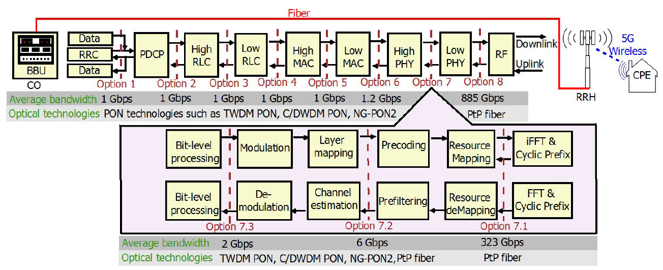
Figure 2. Functional Split Options [12]

The most important thing here is that the bandwidth required for the transport network varies with the functional split option. For example, under average 5G data rates, Option 1 where all functionalities are implemented at the cell site/RRH requires 1 Gbps of bandwidth in the transport (x-haul) link as we only need to transmit packetized processed data. On the other hand, if we use Option 8 where all the functions are centralized at BBU we need more than 800 Gbps on the transport link [10]. In Options 1-6, the bandwidth requirement scales with the number of active users and their traffic because only upper layer functions are centralized, while physical layer functions stay in the RRH. However, after Option 6, bandwidth requirement of x-haul increases exponentially as the bandwidth requirement depends on the physical parameters such as number of antenna ports because now, we move the physical layer functions to the BBU.

Now the challenge is to find the cost-effective and efficient transport network solution because different optical technologies can be used in the transport network depending on the x-haul bandwidth requirement. For example, up to Option 7.3, we can use the cost-effective point to multipoint (PMP) optical links such as passive optical networks (PON) and low data rate point to point (PtP) optical links. However, beyond Option 7.3, we have to use multiple high capacity PtP optical links [11]. In order to achieve the cost-effectiveness and effective operation, we now need to deploy several functional split options and optical technologies in a single network. This is a major challenge.

Therefore, we developed a generalized optimization framework that can be used to jointly plan both 5G wireless and optical transport network for all the functional split options whilst satisfying diverse network requirements such as coverage and capacity. Our framework is also capable of leveraging the resources associated with existing infrastructure to reduce cost and can be used in situations where we have limited availability of existing fiber resources. So that we can apply the framework to analyze the deployment cost and optimally plan the network under any given scenario and to identify the most effective design option. We develop the framework as an integer linear program. In this article, we present an overview of the framework. The details of the mathematical formulation of the framework can be found in [12].

Optical Fig3

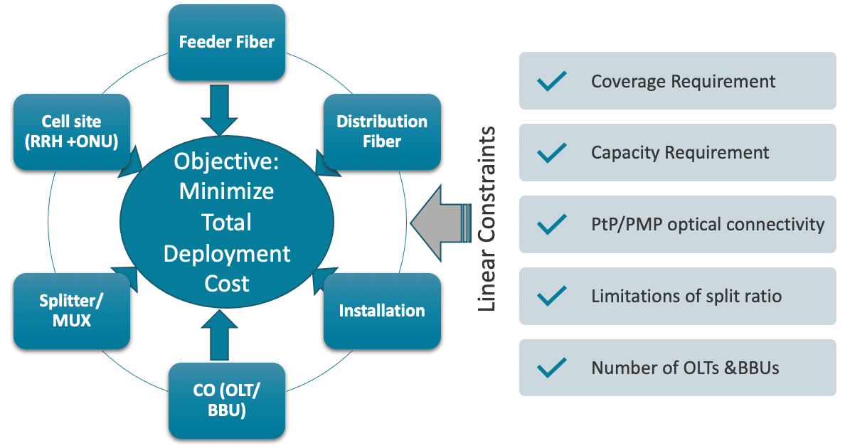
Figure 3. The Optimization framework

Figure 3 illustrates the major components of the framework. As can be seen, the objective of the model is to minimize the total deployment cost of both 5G and its optical transport network. The total deployment cost consists of the cost of feeder fiber, the cost of distribution fiber (deployment of new fiber routes including trenching), the cost of equipment and installations we need at several locations such as CO (BBU, Optical line terminal (OLT) and line cards), splitter location (Splitter /MUX) and cell site (RRH and Optical network unit (ONU)). The framework also consists of multiple constraints to satisfy the network requirements such as coverage, capacity, split ratios, PtP/PMP connectivity and number of BBUs and OLTs in one location. The framework outputs the optimal locations of RRH/ONUs, splitters/MUXs, BBU placement and optimal fiber routes to deploy transport network.

3. Evaluating effectiveness of planning strategies

Optical Fig4

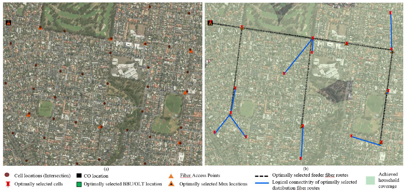
Figure 4. (a) Data set (b) Example of an optimal solution

We then validate our framework by using it to plan 5G and its optical transport network for a suburban area in Eastern Australia. The map of the considered suburban area with over 6000 residents is shown in Fig. 4 (a). The major intersections shown in brown dots are the possible locations for cell deployment, where a light pole/traffic light pole can be used to easily deploy small cells. Orange triangles are the existing fiber access points which are considered as the possible locations for splitter/MUX deployment and black squares are the locations of existing COs. The cost components we applied for the analyses can be found in [12].

We use CPLEX to solve the framework under diverse deployment scenarios considering the fixed wireless access deployment. For example, Fig. 4 (b) shows the optimal solution for the deployment scenario when we have functional split Options 1 to 6, dense wavelength division multiplexing (DWDM) PON as the transport network, RRHs have 300m radius and set the coverage requirement to 99% and per household capacity requirement to 25 Mbps. Figure 4 (b) shows the optimally selected locations for BBU, MUX, RRHs and fiber routes. Feeder fibers are optimally selected from the set of existing fiber network (black dotted lines) and the blue lines show the logical connectivity of optimally selected distribution fiber links that connect the optimally selected RRHs with the selected MUX locations.

We also analyzed the optimal deployment cost under different deployment scenarios as we wanted to find how the optimal cost varies with network requirements such as capacity, cell radius, coverage, and functional splits. Here, we highlight two sets of results. Figure 5 shows the normalized optimal cost under different optical transport networks and different cell radius. In this scenario, we set the coverage requirement to 99% and per user capacity requirement to 50 Mbps. We also consider different splits of DWDM PON and look at how the deployment cost is distributed among optical x-haul and wireless network. It can be seen that x-haul contributes to higher cost compared to the wireless network. For all the cell radius considered, 10G DWDM PON options save 30% of the deployment cost compared to the 10G PtP deployment.

Optical Fig5

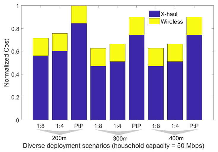
Figure 5. Optimal cost with 10G WDM PON and PtP used as a transport network with coverage 99%

Optical Fig6

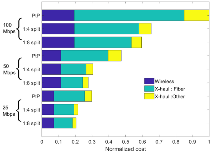
Figure 6. Optimal Cost Vs. Capacity requirement

Figure 6 shows how the deployment cost varies when we have diverse user capacity requirements. We considered a cell radius of 200m and both PtP and 10G PON-based transport network options were analyzed. As expected, the deployment cost increases when the capacity requirement increases. However, the deployment cost of PON-based option is significantly lower compared to the PtP scenario and the cost difference increases with the capacity requirement. For example, at 100 Mbps, the PON-based option saves more than 40% of the deployment cost compared to the PtP case. It is also clear that the main cost contributor among all the deployment scenarios is the installation/use of fiber routes.

After analyzing our results, we have identified that functional split Options 1-6 utilizing PON-based solution can save 30-40% of deployment cost compared to Option 7.2. The details of the evaluation results can be found in [12]. Most importantly, we developed a tool that can be used to optimally plan a 5G/6G and its transport network by simply entering the relevant cost values and the network requirements such as expected coverage percentage, capacity and split ratio.

4. Conclusion
This article highlighted the importance of joint optimal planning of optical transport and wireless networks considering the diverse network requirements in realizing cost-effective deployment of emerging mobile networks. We presented a versatile framework that can be used to provide a cost optimal solution irrespective of the functional split or optical technology in use. The research work presented in the article provide insight into best network design strategies that can be used in planning and dimensioning of optical transport networks for 5G and beyond networks.

Source: https://futurenetworks.ieee.org/tech-focus/april-2021/rethinking-of-optical-transport-network-design-for-5g-6g-mobile-communication 20 04 21

The importance of interoperability testing for O-RAN validation

6 Apr
Being ‘locked in’ to a proprietary RAN has put mobile network operators (MNOs) at the mercy of network equipment manufacturers.

Throughout most of cellular communications history, radio access networks (RANs) have been dominated by proprietary network equipment from the same vendor or group of vendors. While closed, single-vendor RANs may have offered some advantages as the wireless communications industry evolved, this time has long since passed. Being “locked in” to a proprietary RAN has put mobile network operators (MNOs) at the mercy of network equipment manufacturers and become a bottleneck to innovation.

Eventually, the rise of software-defined networking (SDN) and network function virtualization (NFV) brought to the network core greater agility and improved cost efficiencies. But the RAN, meanwhile, remained a single-vendor system.

In recent years, global MNOs have pushed the adoption of an open RAN (also known as O-RAN) architecture for 5G. The adoption of open RAN architecture offers a ton of benefits but does impose additional technical complexities and testing requirements.

This article examines the advantages of implementing an open RAN architecture for 5G. It also discusses the principles of the open RAN movement, the structural components of an open RAN architecture, and the importance of conducting both conformance and interoperability testing for open RAN components.

The case for open RAN

The momentum of open RAN has been so forceful that it can be challenging to track all the players, much less who is doing what.

The O-RAN Alliance — an organization made up of more than 25 MNOs and nearly 200 contributing organizations from across the wireless landscape — has since its founding in 2018 been developing open, intelligent, virtualized, and interoperable RAN specifications. The Telecom Infra Project (TIP) — a separate coalition with hundreds of members from across the infrastructure equipment landscape ­—maintains an OpenRAN project group to define and build 2G, 3G, and 4G RAN solutions based on general-purpose hardware-neutral hardware and software-defined technology. Earlier this year, TIP also launched the Open RAN Policy Coalition, a separate group under the TIP umbrella focused on promoting policies to accelerate and spur adoption innovation of open RAN technology.

Figure 1. The major components of the 4G LTE RAN versus the O-RAN for 5G. Source: Keysight Technologies

In February, the O-RAN Alliance and TIP announced a cooperative agreement to align on the development of interoperable open RAN technology, including the sharing of information, referencing specifications, and conducting joint testing and integration efforts.

The O-RAN Alliance has defined an O-RAN architecture for 5G and has defined a 5G RAN architecture that breaks down the RAN into several sections. Open, interoperable standards define the interfaces between these sections, enabling mobile network operators, for the first time, to mix and match RAN components from several different vendors. The O-RAN Alliance has already created more than 30 specifications, many of them defining interfaces.

Interoperable interfaces are a core principle of open RAN.  Interoperable interfaces allow smaller vendors to quickly introduce their own services. They also enable MNOs to adopt multi-vendor deployments and to customize their networks to suit their own unique needs. MNOs will be free to choose the products and technologies that they want to utilize in their networks, regardless of the vendor. As a result, MNOs will have the opportunity to build more robust and cost-effective networks leveraging innovation from multiple sources.

Enabling smaller vendors to introduce services quickly will also improve cost efficiency by creating a more competitive supplier ecosystem for MNOs, reducing the cost of 5G network deployments. Operators locked into a proprietary RAN have limited negotiating power. Open RANs level the playing field, stimulating marketplace competition, and bringing costs down.

Innovation is another significant benefit of open RAN. The move to open interfaces spurs innovation, letting smaller, more nimble competitors develop and deploy breakthrough technology. Not only does this create the potential for more innovation, it also increases the speed of breakthrough technology development, since smaller companies tend to move faster than larger ones.

Figure 2. Test equipment radio in the O-RAN conformance specification.

Other benefits of open RAN from an operator perspective may be less obvious, but no less significant. One notable example is in the fronthaul — the transport network of a Cloud-RAN (C-RAN) architecture that links the remote radio heads (RRHs) at the cell sites with the baseband units (BBUs) aggregated as centralized baseband controllers some distance (potentially several miles) away. In the O-RAN Alliance reference architecture, the IEEE Radio over Ethernet (RoE) and the open enhanced CPRI (eCPRI) protocols can be used on top of the O-RAN fronthaul specification interface in place of the bandwidth-intensive and proprietary common public radio interface (CPRI). Using Ethernet enables operators to employ virtualization, with fronthaul traffic switching between physical nodes using off-the-shelf networking equipment. Virtualized network elements allow more customization.

Figure 1 shows the layers of the radio protocol stack and the major architectural components of a 4G LTE RAN and a 5G open RAN. Because of the total bandwidth required and fewer antennas involved, the CPRI data rate between the BBU and RRH was sufficient for LTE. With 5G,  higher data rates and the increase in the number of antennas due to massive multiple-input / multiple-output (MIMO) means passing a lot more data back and forth over the interface. Also, note that the major components of the LTE RAN, the BBU and the RRH, are replaced in the O-RAN architecture by O-RAN central unit (O-CU), the O-RAN distributed unit (O-DU), and the O-RAN radio unit (O-RU), all of which are discussed in greater detail below.

The principles and major components of an open RAN architecture

As stated earlier (and implied by the name), one core principle of the open RAN architecture is openness — specifically in the form of open, interoperable interfaces that enable MNOs to build RANs that feature technology from multiple vendors. The O-RAN Alliance is also committed to incorporating open source technologies where appropriate and maximizing the use of common-off-the-shelf hardware and merchant silicon while minimizing the use of proprietary hardware.

A second core principle of open RAN, as described by the O-RAN Alliance, is the incorporation of greater intelligence. The growing complexity of networks necessitates the incorporation of artificial intelligence (AI) and deep learning to create self-driving networks. By embedding AI in the RAN architecture, MNOs can increasingly automate network functions and minimize operational costs. AI also helps MNOs increase the efficiency of networks through dynamic resource allocation, traffic steering, and virtualization.

The three major components of the O-RAN for 5G (and retroactively for LTE) are the O-CU, O-DU, and the O-RU.

  • The O-CU is responsible for the packet data convergence protocol (PDCP) layer of the protocol.
  • The O-DU is responsible for all baseband processing, scheduling, radio link control (RLC), medium access control (MAC), and the upper part of the physical layer (PHY).
  • The O-RU is the component responsible for the lower part of the physical layer processing, including the analog components of the radio transmitter and receiver.

Two of these components can be virtualized. The O-CU is the component of the RAN that is always centralized and virtualized. The O-DU is typically a virtualized component; however, virtualization of the O-DU requires some hardware acceleration assistance in the form of FPGAs or GPUs.

At this point, the prospects for virtualization of the O-RU are remote. But one O-RAN Alliance working group is planning a white box radio implementation using off-the-shelf components. The white box enables the construction of an O-RU without proprietary technology or components.

Interoperability testing required

While the move to open RAN offers numerous benefits for MNOs, making it work means adopting rigorous testing requirements. A few years ago, it was sufficient to simply test an Evolved Node B (eNB) as a complete unit in accordance with 3GPP requirements. But the introduction of the open RAN and distributed RANs change the equation, requiring testing each component of the RAN in isolation for conformance to the standards and testing combinations of components for interoperability.

Why test for both conformance and interoperability? In the O-RAN era, it is essential to determine both that the components conform to the appropriate standards in isolation and that they work together as a unit. Skipping the conformance testing step and performing only interoperability testing would be like an aircraft manufacturer building a plane from untested parts and then only checking to see if it flies.

Conformance testing usually comes first to ensure that all the components meet the interface specifications. Testing each component in isolation calls for test equipment that emulates the surrounding network to ensure that the component conforms to all capabilities of the interface protocols.

Conformance testing of components in isolation offers several benefits. For one thing, conformance testing enables the conduction of negative testing to check the component’s response to invalid inputs, something that is not possible in interoperability testing. In conformance testing, the test equipment can stress the components to the limits of their stated capabilities — another capability not available with interoperability testing alone. Conformance testing also enables test engineers to exercise protocol features that they have no control over during interoperability testing.

The conformance test specification developed by the O-RAN Alliance open fronthaul interfaces working group features several sections with many test categories to test nearly all 5G O-RAN elements.

Interoperability testing of a 5G O-RAN is like interoperability testing of a 4G RAN. Just as 4G interoperability testing amounts to testing the components of an eNB as a unit, the same procedures apply to testing a gNodeB (gNB) in 5G interoperability testing. The change in testing methodology is minimal.

Conformance testing, however, is significantly different for 5G O-RAN and requires a broader set of equipment. For example, the conformance test setup for an O-RU includes a vector signal analyzer, a signal source, and an O-DU emulator, plus a test sequencer for automating the hundreds of tests included in a conformance test suite. Figure 2 shows the test equipment radio in the O-RAN conformance test specification.

Conclusion: Tools and Methodologies Matter

As we have seen, the open RAN movement has considerable momentum and is a reality in the era of 5G. while the adoption of open RAN architecture brings significant benefits in terms of greater efficiency, lower costs, and an increase in innovation. However, the test and validation of a multi-vendor open RAN is no small endeavor. Simply cobbling together a few instruments and running a few tests is not an adequate solution. Testing each section individually to the maximum of its capabilities is critical.

Choosing and implementing the right equipment for your network requires proper testing with the right tools, methodologies, and strategies.

Source: https://www.ept.ca/features/the-importance-of-interoperability-testing-for-o-ran-validation/ 06 04 21

Meet the 5G Alternative: pCell

6 Feb
There’s a reason the US wireless operators just coughed up $45 billion on spectrum and that 5G is getting so much attention: Operators have a ceaseless need for more capacity in this age of smartphones, tablets and the Internet of Things. (See Hey Big Spenders! AT&T, Dish & VZ Splash Cash on Spectrum and Ericsson Testing 5G Use Cases, CFO Says.)

If you need further proof, look to Cisco Systems Inc. (Nasdaq: CSCO)’s venerable Visual Networking Index (VNI) released today, citing that mobile users across the globe cannot get enough of data, with 2.5 exabytes being consumed per month in 2014, a number Cisco expects to rise to 25 exabytes per month in 2019. An exabyte is one billion gigabytes or, in layman’s terms, a butt-load of data. (See Cisco’s Visual Networking Index and Cisco’s VNI Shines Light on Mobile Offload.)

I recently spoke with the CEO of an interesting startup that’s not waiting for 5G standards to be fleshed out, nor even hitching his technology to the 5G hype-wagon. He’s promising a solution to the spectrum crunch that is readily available today. The company is Artemis, and the technology is pCell, a centralized-radio access network (C-RAN) architecture Steve Perlman invented to use cell signal interference to bring high-power signals to individual mobile users.

The company isn’t new — it launched its product with a big PR splash last year, and it’s been working on the technology a decade longer than that. But Perlman says it’s finishing trials and testing now and gearing up for actual deployments. He attributes the lag time to getting over the credibility hump.

Indeed, the startup has had a tough time convincing operators that its technology works as advertised, bringing 25 times performance improvement from the same spectrum and the same devices they’re already using for LTE, without increasing costs substantially. He says that operators still can’t wrap their heads around it even when he shows them the technology working in front of their own eyes.

Analysts we spoke with shared the operators’ disbelief and added their own concerns about standards, scalability and working in the real world. The proof will be in the deployments that Perlman says are coming this year.

In the meantime, read up on pCell in our Prime Reading feature section hereon Light Reading to learn more about the technology, the promise and the challenges and to judge for yourself whether pCell is too good to be true or the magic bullet operators have been searching for. (See pCell Promises to Fix Spectrum Crunch Now.)

Source: http://www.lightreading.com/mobile/fronthaul-c-ran/meet-the-5g-alternative-pcell/a/d-id/713490?

SK Telecom’s Network Evolution Strategies: Carrier aggregation, inter-cell coordination and C-RAN architecture

8 Oct

SK Telecom is the #1 mobile operator in Korea, with sales of KRW 16.6 trillion (USD 15.3 billion) in 2013, and with 50.1% of a mobile mobile subscription market share in 2Q 2014. It launched LTE service back in July 2011, and now more than half of its subscribers are LTE service subscribers, with 55.8% of LTE penetration as of 2Q 2014.
Due to LTE subscription growth, more advanced device features, and high-capacity contents, LTE networks are experiencing an unprecedented surge in traffic. To accommodate the flooded traffic, SK Telecom adopted LTE-A (Carrier Aggregation, CA) in 2013, and Wideband LTE-A (Wideband CA) in 2014 for improved network capacity.
As another effort to increase network capacity, the company made LTE/LTE-A macro cells a lot smaller, as small as hundreds of meters long, resulting in an increased number of cell sites. To save costs of building and operating the increased number of cell sites, it has built C-RAN (Advanced-Smart Cloud Access Network, A-SCAN, as called by SK Telecom) through BBU concentration since January 2012.
In 2014, SK Telecom began to introduce small cells (low-power small RRHs) in selected areas. As with macro cells, small RRHs have the same C-RAN architecture where they are connected to concentrated BBU pools through CPRI interfaces. SK Telecom calls it “Unified RAN (Cloud and Heterogeneous)”.
To prevent performance degradation at cell edges caused by introduction of small cells, SK Telecom developed HetNet architecture (known as SUPER Cell) where macro cells cooperate with small cells. The company, aiming to commercialize 5G networks in 2020, plans to commercialize SUPER Cell first in 2016, as a transitional phase to 5G networks.


Figure 1. SK Telecom’s Network Evolution Strategies
We analyzed SK Telecom’s network evolution strategies using the following three axes: 1) Carrier Aggregation (CA), 2) Inter-Cell Coordination, and 3) RAN Architecture in the Figure 1. Here, the CA axis shows how speeds have been and can be increased (n times) by expanding total frequency bandwidth aggregated. The Inter-Cell Coordination axis displays the company’s strategy to achieve higher speeds at cell edges by improving frequency efficiency. Finally, the RAN Architecture axis shows SK Telecom’s plan to switch to an architecture that would yield better LTE-A performance at reduced costs of building and operating RAN. Figure 2 is SK Telecom’s evolved LTE-A network, as illustrated according to the evolution strategies shown in Figure1.


Figure 2. SK Telecom’s LTE-A Evolution Network 


1. CA Evolution Strategies
CA is a technology that combines up to five frequencies in different bands to be used as one wideband frequency. It allows for expanded radio transmission bandwidth, which would naturally boost transmission speeds as much as the bandwidth is expanded. So, for example, if bandwidth is increased n times, then so is the transmission speed. Table 1 shows the LTE frequencies that SK Telecom has as of September 2014, totaling 40 MHz (DL only) across three frequency bands, which operate as Frequency Division Duplexing (FDD).
SK Telecom commercialized CA in June 2013 for the first time in the world, and then Wideband CA a year later in June 2014. 


It is now offering a maximum speed of 225 Mbps through the total 30 MHz bandwidth. As of May 2014, out of the total 15 million LTE subscribers, 3.5 million (23%) subscribers are using CA-enabled devices. Let’s see where SK Telecom’s CA is heading.


1.1 Combining More Bands: 3-band CA
3-band CA combines three frequency bands, instead of the current two, for wider-band transmission. Currently, SK Telecom has three LTE frequency bands, and is offering 2-band CA of 20 MHz or 30 MHz by combining two of the bands at once. This is because, although LTE-A standards technically support combining of up to five frequency bands, RF chips in  CA-enabled mobile devices available now can support combining of two bands only.  
3-band LTE devices are on the way and will be arriving in the market soon – sometime in early 2015 or by late 2014 at the latest. So, SK Telecom is planning to commercialize 3-band CA that combines all of its three frequency bands, just in time. The commercialization of 3-band CA is expected to increase transmission bandwidth to 40 MHz and data transmission rate to 300 Mbps. SK Telecom is also planning to combine three 20 MHz bands to further expand transmission bandwidth up to 60 MHz, and boost data transmission rate to 450 Mbps.


1.2 Femto Cell with CA
SK Telecom commercialized LTE Femto cell for the first time in the world in June 2012, to provide indoor users with more stable communication quality, and now is attempting to apply CA technology to Femto cell as well. The company completed a technical demonstration of LTE-A Femto cell in MWC 2014, proving it is capable to support 2-band CA. It will be conducting trial tests in a commercial network in late 2014 for final commercialization of the technology in 2015.


1.3 Combining Heterogeneous Networks: LTE-Wi-Fi CA
In July 2014, SK Telecom performed a technical demonstration of heterogeneous CA that combines LTE and Wi-Fi bands by using multipath TCP (MPTCP), an IETF standard. MPTCP is designed to combine more than one TCP flow (or MPTCP subflow) to make a single MPTCP connection, and send data through it. This technology is applied to a device and application server. In the demonstration, an MPTCP proxy server was used instead of an application server (Figure 3).    


Figure 3. LTE – Wi-Fi CA using Multipath TCP (MPTCP)
This technology will allow SK Telecom to combine i) its LTE bands that are currently featuring 2-band CA and ii) 802.11ac-based Giga Wi-Fi bands, together offering up to 1 Gbps or so. 
The detailed commercialization timeline is to be determined in accordance with the company’s plan for future development of MPTCP device and server.


1.4 Combining Heterogeneous LTE Technologies: FDD-TDD CA
This method enables operators to expand transmission bandwidth by combining two different types of LTE technologies: FDD-LTE and TDD-LTE. In a demonstration performed in Mobile Asia Expo in June 2014, SK Telecom successfully demonstrated FDD-TDD CA using ten 20 MHz bandwidths and 8×8 MIMO antenna showing 3.8 Gbps throughout. 

Source: http://www.netmanias.com/en/?m=view&id=blog&no=6647

Quick Insight: Cloud RAN (C-RAN)

24 Oct

Presentation2

As all Telco engineers know that in a typical mobile deployment, each base station serves all the mobile devices within its reach. Each base station has its digital component manage its radio resources, handoff, data encryption and decryption and an RF component which transforms the digital information into analog RF. The RF elements are connected to a passive antenna that transmits the signals to the air. Each base station should be placed in the geographical center of its coverage area. But even when such locations are selected, the mobile operators may have difficulty in renting the real estate, finding proper powering options, securing the location and protecting the equipment from weather conditions. Those cell sites carry with them a continuous stream of OPEX to address the high rental rates for real estate, electrical expenses, cost of backhaul for the cell site and security measures to protect the location from intruders.

Enter the latest architectural paradigm : C RAN !!! The basic premise of Cloud RAN is to change the traditional RAN architecture so that it can take advantage of technologies like cloud computing, Software-Defined Network (SDN) approaches, and advanced remote antenna/radio head techniques.C-RAN architecture is not bound to a single RAN air interface technology. In essence, conventional terrestrial cell site base stations are replaced with remote clusters of centralized virtual base stations which can support up to a hundred remote radio / antenna units. This is achieved by centralizing RAN functionality into a shared resource pool or “cloud” (the digital unit – DU, or baseband unit – BBU) which is then connected via fibre to advanced remote radio heads (“Radio Units” – RU) sited in different geographical locations in order to provide full coverage of an area. The radical concept can even use banks of x86 servers to connect cellular calls rather than traditional wireless base stations.

From a business perspective,C-RAN will deliver significant reductions in Opex and Capex due to reduced upgrading costs. A major reason for this is the aggregation and pooling of the DU computing power which can be assigned specifically where needed e.g. the load situation over time and space for indoor/outdoor cells, am/pm hours, weekday/weekend, and so on. As a result, single cells do not need to be dimensioned for peak hour demands, but rather the processing power can be pooled and assigned on an on-demand basis. The processing power savings achieved should also leave processing headroom for any further potential technology enhancements (e.g., LTE-A features) without the need for further CAPEX. C-RAN skips the need for a high-bandwidth, low latency (X2), synchronized interface between the geographically distributed base station because the computing resources of the multiple transmission points’ BBUs are all located within the same hardware.

Furthermore, interference management will also benefit from C-RAN network architecture as technologies like dynamic eICIC schemes will be enabled, especially in a HetNet deployment.Heterogeneous networks will require small cells to be independent, intelligent and ubiquitous to avoid the cross- interference mayhem, yet be in synch and orchestrated with macro cells (including Cloud – RAN topology).Small cells are poised to become the most commonly used node for cellular access in the next-generation HetNet. C RANs will likely take their place beside traditional base stations and emerging small-cell base stations as another tool for building cellular nets.

According to Maravedis Cloud-RAN economics only be realized by harnessing standards to ensure interoperability and reduce cost. That, in turn, will create a whole new ecosystem, and operators must resist any attempts by their suppliers to hijack standards for software-defined networking or cell site equipment. Otherwise, this fledgling architecture will remain confined to a few pioneers with the resources to build their own ecosystems, like China Mobile.

China Mobile, the world’s largest carrier with 700 million subscribers, has been spearheading trials and plans to deploy systems as early as 2015. Japan’s NTT Docomo said it will follow in 2016, and a third unnamed carrier is now preparing plans for C-RANs. China Mobile aims to lower the cost of C-RANs to less than $30 per LTE sector, down from about $10,000 two years ago. It will start a second round of trials later this year using servers equipped with PCI Express cards to handle baseband processing. Each card will pack four FPGAs using silicon cores, each FPGA capable of handling 12 LTE sectors.

Pure C-RAN faces many barriers, such as over-reliance on fiber to link sites and basebands and immature standards, but most operators will inch towards C-RAN using hybrid models. Development of microwave fronthaul technologies will be critical to improve the C-RAN business model . Whatever the challenges C-RAN offers a revolutionary approach to next-generation cellular networks deployment, management and performance.

As MNOs face rising CAPEX bills to meet mobile data demand combined with falling ARPU, they must explore radical new network designs. With Cloud-RAN, they can virtualize baseband processing functions for hundreds of sites on a server or base station hotel. By consolidating individual Base-station processing into a single or regional server farm Investments on Cloud Radio Access Network (RAN) Infrastructure are expected to exceed $6 Billion by 2020, according to a new report from SNS Research. Distributed antenna technologies ( DAS ) will get a new lease on life, supporting coverage extension for C-RAN sites. This sector will open up $1.3bn in new revenues for antenna providers.

Sadiq Malik ( Telco Strategist )

Source: http://maliksadiq13.wordpress.com/2013/10/23/quick-insight-cloud-ran-c-ran/

Improving Capacity Coverage at the Network’s Edge

7 Aug

While all the commotion is in the small cell domain, let’s look at a traditional tail site and see what are the main ideas for capacity coverage improvement.

Just seven years ago, a tail site was connected with a single DS1 or E1. With LTE, we went up to 100-150 Mbps per site. Now we’re pitching 1Gbps per tail site. Mainly because LTE-Advanced can deliver 1Gbps using 100 MHz of spectrum with carrier aggregation.

Improvinf Capacity Coverage

The first question that arises in the minds of network engineers is, “Where am I supposed to get 100 MHz of spectrum?” The main option today is to re-farm old 2G and 3G spectrum to gain better spectral efficiency with  new gear.  The second option is to bid for new channels such as LTE3500. Upon release, 3.5GHz LTE will bring with it a potential 400 MHz for distribution in many countries.  In the meantime, the eco-system is not there yet but with 200MHz in FDD, 200 MHz in TDD – it is safe to say that it is likely to happen.

Higher spectrum is not very efficient for coverage but it is the right choice for small cells and tail sites.  We can reuse this spectrum many times due to its short range.  This spectrum was sub-optimal for WiMAX because it didn’t go very far but for small cells or a tail site that is covering a small area, 3.5GHz  is an excellent spectrum.

But this does not conclude all my capacity requirements in this particular location.  I am likely to have a RAN sharing model one way or another, with more than one mobile operator. This sharing concept requires a short explanation. The obvious trends are whole operations sharing such as EE in UK or a backhaul joint venture such as NetShare in Ireland. However the case of backhaul service provides (Carriers of Carriers – CoC or alternate access vendors – AAV) is very similar – it its about transparency and service differ nation. But it also means a need to serve additional spectrum slices per site in terms of capacity or marinating a more sophisticated timing scheme

And even more interesting, this is considered to be the best place to aggregate all my other small cells.  My offload, integrated, coordinated models, not to mention more sectors connected to a tail site –  aka, Distributed Base Station as we discussed in my past post.

All of these capacity requirements surface as this is my point of presence.  However, when we start talking about coordinated multi-point capabilities and carrier aggregation (CoMP). More coordination between the sites means higher capacities and lower latencies. Though it has yet to be seen how to implement these concepts in an ideal or non-ideal backhaul environment.  So in essence, it’s easy to see that 1 Gbps is going to be the new E1 for a tail site.

Stay tuned for part three of this conversation where I will discuss taking the distribution concept to the extreme with a move to Cloud-RAN (C-RAN).

In the meantime, for more information on how to increase capacity coverage, feel free to take a moment to view Ceragon’s new white paper on Capacity Coverage or feel free to reach out to me with any questions at rana@ceragon.com.

Source: http://backhaulforum.com/traditional-tail-site-and-the-main-ideas-for-improving-capacity-coverage/

Cloud RAN Attracts Asian, European Carriers

17 Jul
SAN JOSE, Calif.— Three service providers are working on plans to deploy cloud radio access networks (C-RANs), a new approach to building cellular networks. The radical concept uses banks of x86 servers to connect cellular calls rather than traditional wireless base stations.

China Mobile, the world’s largest carrier with 700 million subscribers, has been spearheading trials and plans to deploy systems as early as 2015. Japan’s NTT Docomo said it will follow in 2016, and a third unnamed carrier is now preparing plans for C-RANs, said Gilad Garon, chief executive of Asocs Ltd. which sells silicon cores for modems.

“In last few months any doubts whether C-RAN would happen have gone away,” said Garon, whose company was chosen in February to supply baseband technology for China Mobile’s trials, in an interview. “Korea Telecom is involved, and we see interest in Europe primarily from Deutsche Telekom.”

China Mobile aims to lower the cost of C-RANs to less than $30 per LTE sector, down from about $10,000 two years ago. It will start a second round of trials later this year using servers equipped with PCI Express cards to handle baseband processing. Each card will pack four FPGAs using Asocs cores, each FPGA capable of handling 12 LTE sectors, said Garon.

The trial also will test Asocs’ MPL, a programming language for baseband chips. MPL lets developers call C-language libraries that will run jobs on ARM, Mips or x86 processors.

The next trial will use only Intel servers, but emerging low power ARM servers could be used in C-RANs in the future. “There’s still the cost of optics, software and servers, but the sheer DSP processing will be cheap,” said Garon.


Asocs' CR2100 cores will link to Intel Xeon chips in China Mobile's next C-RAN trial.

Asocs’ CR2100 cores will link to Intel Xeon chips in China Mobile’s next C-RAN trial.


C-RANs will likely take their place beside traditional base stations and emerging small-cell base stations as another tool for building cellular nets, said Gordon Mansfield, chairman of the Small Cell Forum and executive director of small cell solutions and radio access network delivery at AT&T Mobility.

“C-RANs’ biggest challenge is backhaul,” said Mansfield. “It requires extreme low latency and that requires fiber” which is expensive and not widely deployed in many parts of the world where traditional and small cells will be a better fit, he said.

With the exception of Intel, C-RANs also lack the support of the major chip makers, Mansfield, said. “Having general purpose hardware and software is the ultimate goal, and all the big, heavy-processing silicon providers will end up there I believe, but right now it’s too early to see who will come out as leaders,” he added.

Source: http://www.eetimes.com/document.asp?doc_id=1318782&itc=eetimes_sitedefault&goback=%2Egmp_136744%2Egde_136744_member_258153936%2Egmp_136744%2Egde_136744_member_258637325%2Egmp_136744%2Egde_136744_member_258645944%2Egmp_136744%2Egde_136744_member_258645944%2Egmp_136744%2Egde_136744_member_258637325%2Egmp_136744%2Egde_136744_member_258537210