

Goal: The following describes how to use SSH and the MediaTek Cloud Sandbox to deploy firmware over-the-air (FOTA) updates to a MediaTek LinkIt Smart 7688 Duo intelligent gateway development platform in a matter of minutes. The demo begins by testing the LinkIt Smart 7688 Duo hardware by programming a ‘Blink’ application in Python and delivering it through the OS X Terminal application, and verifying the board’s connectivity by pinging a server there as well. Afterward, a prototype and test device are created in the MediaTek Cloud Sandbox, and a Node.js program is installed on the LinkIt platform enabling it to communicate with the MediaTek Cloud Sandbox API. Finally, a separate Python ‘Blink’ program with a different time delay is developed in the Arduino Software IDE and uploaded to the cloud platform before being pushed over the air to the Atmel ATmega32U4 MCU that drives LED D13 on the LinkIt Smart 7688 Duo.
(Note: The following uses a Mac implementation using Terminal for SSH, though instructions for Windows (PuTTY) and Linux can be found in the Developer’s Guide)
What you’ll need:
- MediaTek LinkIt Smart 7688 Duo development board
- MediaTek Cloud Sandbox account
- Arduino Software Integrated Development Environment (Version 1.6.7 used here)
- Micro USB cable
Cost:
- LinkIt Smart 7688 Duo – $15.90 plus shipping and handling from Seeed Studio
Checking the hardware and cutting to the chase
Connectivity check
Step-by-step instructions for configuring the LinkIt Smart 7688 Duo development board and connecting it to the Internet via a local network are available online, so let’s skip ahead to testing the device’s Internet connection and hardware, namely the onboardAtmel ATmega32U4 MCU that we’ll be programming to drive LED D13.

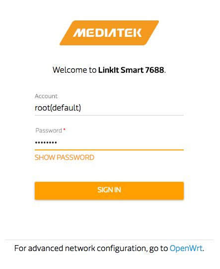
Once the board is plugged in, configured, and connected, you’ll need to access a command line interface (CLI) of your PC, which on OS X can be done using the Terminal application. Now that you’ve got access to the CLI, access the board’s operating system by typing ssh root@mylinkit.local and entering the password you previously created for the web-based mylinkit.local dashboard (this one). After successfully SSHing into the board, you will see the OpenWrt welcome message, which incidentally also provides a Chaos Calmer drink recipe, as below.

(Note: If you receive an error message indicating that the host ID has changed, reference the troubleshooting section of the LinkIt Smart 7688 Developer’s Guide on page 95).
Now you’ll be able to issue commands to the LinkIt Smart 7688 Duo through the system console, so let’s first check that the board is connected to the Internet. After root@mylinkit.local:~# in the command line, enter ping –c 5 www.mediatek.com. This tells the board to ping a MediaTek server five times and report back information on the roundtrip travel time, packet loss, etc. If done correctly, you should receive a report similar to the one below.

MCU programming
You know that your board is connected, so it’s time to test the hardware. Download the Arduino IDE if you don’t have it already, and follow the steps in the Developer’s Guide to make sure the LinkIt Smart 7688 Duo board support package is installed correctly and, for Windows users, that the appropriate Serial COM port drivers are installed (Note: The LinkIt Smart 7688 Duo supports Arduino IDE versions 1.6.4 or later, but there’s a known bug with serial port communications in version 1.6.8 when using the LinkIt Smart 7688 Duo so I recommend using version 1.6.7). Next, create a new sketch, paste the following code into the Arduino editor, and upload it to the Duo board:
void setup() {
Serial.begin(115200); // open serial connection to USB Serial //port (connected to your computer) Serial1.begin(57600); // open internal serial connection to //MT7688 pinMode(13, OUTPUT); // in MT7688, this maps to device } void loop() { int c = Serial1.read(); // read from MT7688 if (c != -1) { switch(c) { case ‘0’: // turn off D13 when receiving “0” digitalWrite(13, 0); break; case ‘1’: // turn on D13 when receiving “1” digitalWrite(13, 1); break; } } }
You likely got an error saying that “‘receiving’ was not declared in this scope,” which is fine because we need to create a program that maps the Serial1 commands in the above sketch through the correct port on your PC.

Back in the command line on root@mylinkit:~# type vim blink_on_duo.py to create a Python ‘Blink’ program that you’ll use to test the board’s hardware. After you enter this command, you’ll be taken to a blank text editor that allows you to enter example code, provided by MediaTek. Hit the ‘i’ key to enable insertion, then paste in the following:
import serial import time s = None def setup(): global s # open serial COM port to /dev/ttyS0, which maps to UART0(D0/D1) # the baudrate is set to 57600 and should be the same as the one # specified in the Arduino sketch uploaded to ATMega32U4. s = serial.Serial(“/dev/ttyS0”, 57600) def loop(): #send “1” to the Arduino sketch on ATMega32U4. # the sketch will turn on the LED attached to D13 on the board s.write(“1”) time.sleep(1) # send “0” to the sketch to turn off the LED s.write(“0”) time.sleep(1) if __name__ == ‘__main__’: setup() while True: loop()

After hitting Escape, typing :wq! and pressing the Return key, you’ll be taken back to the command line for root@mylinkit:~#. Type python ./blink_on_duo.py, wait a couple of seconds, and watch for the LED D13 to blink on and off in one second intervals. If it does, you’re all good, and ready to get to the fun stuff.

Testing is the worst! I want to build connected applications!
I know, but the above tests actually have you well on your way to creating a FOTA prototype.
Accessing the MediaTek Cloud Sandbox and creating an additional firmware file with the Arduino IDE
At this point you need to login or register for the MediaTek Cloud Sandbox (MCS). Once you’ve entered the dashboard, select the“Development” dropdown in the upper left of the navigation menu, and click “Prototype.” You’ll be taken to a screen that prompts you to “Create your prototype now!” so do as you’re told and click the blue “Create” button. Enter whatever information you wish into the fields in the ensuing popup window, but make sure you’ve selected“LinkIt Smart 7688 (MT7688)” as the hardware platform (Note: I named my prototype MT_LS7688Duo_1, as you can see below). Click“Save” at the bottom.

Now you’ll see the prototype you’ve just uploaded in the Prototype list, so click the blue “Detail” button beneath it. You’ll now be taken to a new screen with a tooltip wizard that outlines the capabilities of MCS. This dashboard allows you to add data channels, define triggers and actions, implement user privileges, and manage test devices, but what you’ll be focusing on today is the “Firmware” tab. But before you do that, you’re going to need some firmware to upload.
Back in the Arduino IDE, we can quickly pull some example code by navigating to File -> Examples -> Basics -> Blink. A ‘Blink’ sketch will appear, but instead of leaving the delay in the code at 1000 µs (or one second, which is the same interval already running on the 7688 Duo), change the wait time to 250. Remember to update both the HIGH and LOW write directions, and also observe good coding practices by documenting the change in the notes.

Now, instead of uploading this sketch directly to the board, you want to upload it to MCS. So, in the Arduino navigation bar, select the Sketch dropdown and click “Export compiled Binary” (Note: This is where I encountered problems with version 1.6.8). Save this new program somewhere that’s easily accessible, and, if you wish, you can also make an additional firmware file with different time delays for use with MCS.

Returning to the MCS Prototype dashboard, complete or exit the wizard if you haven’t already and navigate to the firmware tab. Select “+Add firmware” below, and fill out the required fields, including your recently created firmware file.

Hit “Upload” at the bottom of that window, and in Step 2 of the“Add firmware” process, click next after making sure only the “All firmware(default)” box is checked. On Step 3 click “Not Now,” for now.
In the upper right-hand corner of the Prototype dashboard, you will now see that the “Create test device” button is illuminated blue. Select it, and enter a device name (Note: I just used “MT_LS7688Duo_1_Test”). Click “Create,” then in the window that follows, select the “Go to detail” option.

The Test Device detail page looks similar to the prototype page, with one key difference: This is where you’ll find the deviceId anddeviceKey needed to call the MCS RESTful APIs (Note: See those provided for my device below).

Prepping the LinkIt Smart 7688 for FOTA with command line Node.js
Back to the Terminal app for the last time, you’ll need to create a new directory (folder) under root@mylinkit.local by entering mkdir app && cd appinto the command line. Once that directory has been created you have to install a couple of Node.js modules on the 7688 Duo by entering npm install mcsjs and npm install superagent in the command line as well. Do each one of them separately, and be patient as each may take a couple of minutes to install, during which time the CLI will appear to be unresponsive (or display a cart-wheeling slash). The end result should look something like this:

Now that you have all of the appropriate Node.js modules installed, we can write a program that allows the 7688 Duo to communicate with MCS. Enter vim app.js in the command line to create a new application file, then, as before with the Python ‘Blink’ program you entered into terminal, press the ‘i’ key to enable insertion and paste in the following code:
var mcs = require(‘mcsjs’); var spawn = require(‘child_process’).spawn; var fs = require(‘fs’); var request = require(‘superagent’); var fwName = ‘fw.hex’; var myApp = mcs.register({ deviceId: ‘Input your deviceID’, deviceKey: ‘Input your deviceKey’, }); var download = function(url, dest, cb) { var file = fs.createWriteStream(dest); var sendReq = request.get(url); // verify response code> sendReq.on(‘response’, function(response) { if (response.statusCode !== 200) { return cb(‘Response status was ‘ + response.statusCode); } }); // check for request errors sendReq.on(‘error’, function (err) { fs.unlink(dest); if (cb) { return cb(err.message); } nbsp; });nbsp; sendReq.pipe(file); nbsp; file.on(‘finish’, function() { nbsp; nbsp; file.close(cb); // close() is async, call cb after close completes. nbsp; }); nbsp; file.on(‘error’, function(err) { // Handle errors fs.unlink(dest); // Delete the file async. (But we don’t check the result) if (cb) { return cb(err.message); } }); }; myApp.on(‘FOTA’, function(data, time) { console.log(data); var Data = data.split(‘,’); var firmwareUrl = Data[2]; download(firmwareUrl, fwName, function(){ var update = spawn(‘avrdude’, [‘-p’, ‘m32u4’, ‘-c’, ‘linuxgpio’, ‘-v’, ‘-e’, ‘-U’, ‘flash:w:/root/’+ fwName, ‘-U’, ‘lock:w:0x0f:m’]); update.stdout.on(‘data’, function(data) { console.log(data) }); update.stderr.on(‘data’, function(data) { console.log(data.toString()) }); ;}); });
But you’re not done yet. This is where the deviceID and deviceKey from the test devices page in MCS come into play, as you need those so the cloud API can identify your LinkIt Smart 7688 Duo platform. Enter these in lines 8 and 9 of the code where it says ‘Input your deviceID’ and ‘Input your deviceKey’ respectively (Note: Leave the quotes on each). When complete, your code should look something like this:

Press Escape on your keyboard and type :wq! to return to the main command line for root@mylinkit.local. To execute the program, enter node app.js there.
Firmware over-the-air for real
Remember the additional firmware file we exported from Arduino and uploaded to MCS? Well, return to the MCS dashboard and navigate to the Test device page if you’re not still there. Notice the green dot next to the name of your test device name in the upper left of the interface indicating that your LinkIt Smart 7688 Duo is connected, then click on the Firmware tab below. The firmware you previously uploaded is still there, only now the “Push” button to the right should be blue. Go ahead and give it a click, wait a couple of seconds, and watch for the change in delay on LED D13 of the LinkIt Smart 7688 Duo from one blink every 2 seconds to one blink per second.

Congratulations, you’ve performed a FOTA update and are officiallyIoT certified!
Comprehensive video tutorial to come, as soon as I get these formats converted!
Source: http://iotdesign.embedded-computing.com/articles/fast-fota-update-tutorial-for-the-internet-of-things/

Leave a comment