Staggered deployment means that next-gen cellular networks will still be vulnerable to the security flaws of 3G and 4G
Photo: iStockphoto
6 Reasons Why IoT Security Is Terrible
There is a lot of excitement over 5G’s promise of blazing speeds, lower latencies, and more robust security than 3G and 4G networks. However, the fact that each network operator has its own timetable for rolling out the next-generation cellular technology means early 5G will actually be a patchwork of 2G, 3G, 4G, and 5G networks. The upshot: For the next few years, 5G won’t be able to fully deliver on its promises.
The fact that 5G networks will have to interoperate with legacy networks means these networks will continue to be vulnerable to attacks such as spoofing, fraud, user impersonation, and denial-of-service. Network operators will continue to rely on GPRS Tunneling Protocol (GTP), which is designed to allow data packets to move back and forth between different operators’ wireless networks, as may happen when a user is roaming (GPRS itself stands for General Packet Radio Service, a standard for mobile data packets.) Telecom security company Positive Technologies said in a recent report that as long as GTP is in use, the protocol’s security issues will impact 5G networks.
GTP was initially introduced during the upgrade from 2G to 3G, and it remains widely used with 4G because it makes it possible to fall back to legacy technologies when a dependable, higher-speed signal is not available. Most operators have GTP so it acts as the common link to seamlessly hand off data packets across networks. When a 5G device switches to 3G or 4G, which it will inevitably do as carriers are deploying 5G in stages, it will be susceptible to attacks exploiting vulnerabilities in GTP.
GTP has a number of well-known, fundamental security flaws that leave networks vulnerable to attack. One of the core flaws is the fact that it does not validate the user’s physical location, making it possible for an attacker to spoof their traffic’s location.
Another flaw is that attackers can impersonate other subscribers, either by stealing credentials or spoofing user session data and a real phone number. Attackers can use this to access network services. The impersonated subscriber may have to pay for charges incurred, or if the attacker used fake credentials, the operator is left on the hook with no one to bill.
Lastly, an attacker can send requests to open up multiple data connections on a single access point in a denial-of-service attack. This attack exhausts the access point’s available connections, so legitimate subscribers are unable to reach the Internet. Because an operator typically supports all its subscribers in a particular region on a single node, an attack against that node could potentially knock all the subscribers in that region offline.
These vulnerabilities aren’t part of the 5G protocol, but most 5G network deployments are non-standalone. Non-standalone means the network interoperates with legacy networks, usually via GTP.
“Faults in the GTP protocol directly impact 5G networks.”
Every discussion of the benefits of 5G—the faster speeds and staggering amounts of data—assumes that every network, or nearly every network, is using 5G. But that’s not how telecom companies are rolling out the next generation of wireless. They are going in stages and focusing on low-band 600-MHz spectrum, primarily because the sheer size of most networks makes it impractical to do a full-scale replacement at once. It will take time to build out the infrastructure to get to that level of capacity and service.
For at least the next few years, 5G networks will be linked to legacy networks in this way, as operators focus on building out 5G in specific areas and connecting those hotspots with a 4G backbone. For example, Verizon Communications CEO Hans Vestberg said during a recent J.P. Morgan investor conference that Verizon has been rolling out 5G in dense urban areas in the United States and will be using 4G and 3G to maintain coverage over rural areas for the time being.
Another reason 5G networks will be non-standalone for the near future is because operators are concerned about interoperability. They have different timetables on how they are going to deploy the infrastructure. Even if one carrier decides to do a wholesale replacement and go straight to 5G, other carriers that it works with may not make that same decision.
And when telecom companies finish their deployments, they’ll still need to implement additional security controls for subscriber authentication and authorization—on top of 5G’s built-in security protections—to address the security gaps in GTP. Even when standalone 5G is in place, GTP vulnerabilities may exist because mobile technologies such as text messaging still rely on GTP.
“Transitions always seem to introduce a certain amount of chewing gum and baling wire to get stuff to work and this is one that’s left over from 3G!”
Operators in Japan and South Korea may be finished with their 5G deployments in five years, but the pace will be slower in Europe and the United States because “there is less inclination” make the shift.
“GTP security issues will not go away completely even after the transition to 5G standalone.”
This page compares SU-MIMO vs MU-MIMO and mentions difference between SU-MIMO and MU-MIMO with respect to 802.11ax (wifi6), 4G/LTE and 5G NR (New Radio) technologies.
Introduction : MIMO refers to multiple input multiple output. It basically refers to system having more than one antenna elements used either to increase system capacity, throughput or coverage. Beamforming techniques are used to concentrate radiated energy towards target UE which reduces interference to other UE’s and thereby improves the coverage.
There are two major types of MIMO with respect how the BS (Base Station) transmission is utilized by the mobile or fixed users. They are SU-MIMO and MU-MIMO. Both the types are used in the downlink direction i.e. from Base Station or eNB or Access point towards users.
There is another concept called massive MIMO or mMIMO in which combines multiple radio units and antenna elements on single active antenna unit. It houses 16/32/64/96 antenne elements. The massive MIMO employs beamforming which directs energy in desired user direction which reduces interference from undesired users.
SU-MIMO
• In SU-MIMO, all the streams of antenna arrays are focused on single user.
• Hence it is referred as Single User MIMO.
• It splits the available SINR between different multiple data layers towards target UE simultaneously where each layer is separately beamformed. This increases peak user throughput and system capacity.
• Here cell communicates with single user.
• Advantages : No interference
The figure depicts SU-MIMO and MU-MIMO concept in IEEE 802.11ax (wifi6) system. It shows wifi6 compliant AP (Access Point) and wifi6 stations or users or clients.
MU-MIMO
• In MU-MIMO, multiple streams are focused on multi users. Moreover each of these streams provide radiated energy to more than one users.
• Hence it is referred as Multi User MIMO.
• It shares available SINR between multiple data layers towards multiple UEs simultaneously where each layer is separately beamformed. This increases system capacity and user perceived throughput.
• Here cell communicates with multi users.
• Advantages : Multiplexing gain
The figure depicts MU-MIMO used in mMIMO system in 5G. As shown multiple data streams (of multiple users) are passed through layer mapping/precoding before they are being mapped to antenna array elements and transmitted over the air.
Tabular difference between SU-MIMO and MU-MIMO
Following table summarizes difference between SU-MIMO and MU-MIMO.
Features
SU-MIMO
MU-MIMO
Full Form
Single User MIMO
Multi User MIMO
Function
It is the mechanism in which information of single user is transmitted simultaneously over more than one data stream by BS (Base Station) in same time/frequency grid (i.e. resources).
In MU-MIMO, data streams are distributed across multiple users on same time/frequency resources but dependent upon spatial separation.
Major Objective
It helps in increasing user/link data rate as it is function of bandwidth and power availability.
It helps in increasing system capacity i.e. number of users supported by base station.
Performance impact (Antenna Correlation)
More susceptible
Less susceptible
Performance Impact (Source of interference)
Adjacent co-channel cells
Links supporting same cell and other MU-MIMO users, and adjacent co-channel cells
Power allocation
Split between multiple layers to same user. Fixed per transmit antenna
Shared between multi-users and multiple layers. It can be allocated per MU-MIMO user based on channel condition.
CSI/Feedback process
Varies upon implementation, TDD or FDD and reciprocity or feedback based. Less susceptible on feedback granularity and quality
Very dependent upon CSI for channel estimation accuracy. More susceptible on feedback granularity and quality
Beamforming dependency
Varies upon implementation TDD or FDD and reciprocity or feedback based. Less susceptible on feedback granularity and quality
Greatly assisted by appropriate beamforming mechanisms (spatial focusing) which maximizes gain towards the intended users. More susceptible on feedback granularity and quality
Time to get schooled on 5G terms.Graphic by Pixabay/Illustration by CNET
If you want to know everything about how 5G works, we’ve got a handy guide for you. But if you want to sound like an expert, this is the place for you.
The following is our glossary of 5G terms.
4G
Before we get into 5G, let’s talk about 4G, the network we’re on today. It stands for the fourth generation of mobile technology, and it launched in late 2010. While 3G networks primarily dealt with phone calls and text messaging, 4G was the first to really emphasize data speeds comparable to those of your home broadband connection. That data focus led to the emergence of the app economy, as well as services like Uber, livestreaming and sophisticated mobile gaming.
5G
5G, of course, stands for the fifth generation of wireless technology. If 4G brought higher speeds, 5G amps that up and allows for the better connection of more devices, including offering variable speeds based on the needs of the connected gadget. A smartphone is going to consume a lot of bandwidth when livestreaming, while an ATM needs an infrequent, but dependable connection.
5G NR
The 5G bit is pretty obvious, but the NR stands for New Radio. You don’t have to know a lot about this beyond the fact that it’s the name of the standard the entire wireless industry has rallied behind.
That’s important because it means everyone is on the same page when it comes to their mobile 5G networks. Carriers like AT&T and T-Mobile are following 5G NR as they build their networks. But Verizon, which began testing 5G as a broadband replacement service before the standard was approved, initially wasn’t using the standard when it launched in late 2018. The company did eventually adopt 5G NR for its broadband service, with its mobile network running on the NR standard too.
Given that everyone is using the same standard, you’ll likely hear the term less. But it’s key to know the name of the technology that serves as the common foundation for 5G networks.
Latency
If speed is the headline benefit, latency is the feature of 5G that many believe will actually drive a lot of the innovation. Latency is the lag time that happens when you click on a link or fire a gun in a mobile game and the phone pings the network and receives a response. You probably noticed a slight hesitation when chatting with someone on Zoom — that’s the lag time as the signals physically travel across great distances.
That lag time can last around 20 milliseconds with current networks. It doesn’t seem like much, but it makes a difference if you need instantaneous response. For anyone playing Fortnite, making sure your character actually shoots when you hit the button is critical.
With 5G, that latency gets reduced to as little as 1 millisecond, or about the time it takes for a flash on a normal camera. The caveat is that lag time can still be a factor if you’re communicating with someone far away.
Spectrum
Spectrum is referred to as the “lifeblood of the wireless industry.” That’s because these radio airwaves, similar to how you get radio channels in your car, are how you also get cellular signals. But you don’t need to tune your phone like a radio to get different channels — your phone is set to automatically tap into the appropriate frequency.
Wireless carriers use spectrum to ferry data over the air, and over time, they’ve gotten better and more efficient at this process.
Wireless carriers each have their own swath of spectrum, which power older 3G and 4G networks. But these companies are looking to secure more spectrum to enable a broader rollout of 5G.
Generally, the higher the band or frequency, the higher the speed you can achieve. The down side of higher frequency, however, is shorter range.
Conversely, the lower the band, the better the range, but there’s a limit to how fast your connection will be.
Millimeter wave
This refers to a really high-frequency spectrum. The millimeter wave range falls between 24 gigahertz and 100 gigahertz. Whenever someone talks about the crazy speeds you get with 5G, they’re often referring to the flavor of 5G running on this kind of spectrum.
The problem with super high-frequency spectrum, besides the short range, is it’s pretty finicky — if a leaf blows the wrong way, you get interference. Forget about obstacles like walls. Companies including Verizon are working on using software and broadcasting tricks to get around these problems and ensure stable connections.
Think about millimeter wave coverage zones as glorified Wi-Fi hotspots with insane speeds. It’s fantastic if you’re in one — just don’t walk too far away.
Low Band
Carriers have been using low-frequency bands for years to power 3G and 4G networks that we use today. Much of the 4G network in the US, for instance, runs on 700 megahertz spectrum. The industry likes using low-band radio airwaves because they travel across great distances and penetrate walls.
But that long range comes at a price. If millimeter wave is one side of the equation with a fat bandwidth pipe, then low-band spectrum sits on the other side, with a limited amount of speed you can place on those airwaves.
Midband
Midband, as its name suggests, sits in between the low and millimeter wave spectrums. It’s considered a “sweet spot” swath of radio frequencies because it has a nice mix of speed and range.
Most of the carriers around the world launched with midband spectrum, but because the US carriers lacked radio airwaves in this frequency, they opted to invest in the flashier and faster millimeter wave technology.
In the US, only T-Mobile has a significant swath of 2.5 GHz midband spectrum, which it obtained from Sprint. In fact, that’s the primary reason why T-Mobile worked so hard to acquire its rival.
There isn’t necessarily one band of spectrum that’s better than the rest. The carriers all understand that they’ll need all three in order to offer complete coverage.
Sub-6 GHz
Sub-6Ghz is a term that generally groups together the low and midband frequencies. Back when a few of the early carriers were talking up millimeter wave, Sub-6 became the alternative path for 5G that allowed carriers to reuse their existing stash of spectrum.
5G E
Sorry, but it’s marketing fluff. AT&T’s 5G E stands for 5G Evolution, its upgraded 4G LTE network that has a path to real 5G.
But the designation, which showed up on phones early in 2019, has caused some consumer confusion, with some thinking they already have 5G. To be clear, it’s not, with many bashing AT&T for misleading customers. Sprint filed a lawsuit against AT&T, which, according to an AT&T spokesperson, the companies “amicably settled.” The National Advertising Review Board has recommended that AT&T stopping using the term in its marketing, although the icon on your AT&T phone remains.
Dynamic spectrum sharing, or DSS, allows a carrier to take spectrum already in use for 4G and allow it to also work for 5G. If a wireless network is like a multilane freeway, DSS would allow a carrier to redesignate lanes as 5G or 4G on the fly based on their specific needs.
In the US this helps providers like AT&T and Verizon which currently don’t have as much free midband or low-band spectrum to offer multiple flavors of 5G. While the technology is useful to T-Mobile as well, the carrier acquired a large chunk of midband spectrum when it completed its merger with Sprint in April.
5G SA
Known as 5G standalone, this is a 5G network that doesn’t rely on a 4G LTE network to provide a backbone. As “true 5G” networks, these deployments have lower latency and even faster speeds.
5G NSA
The early form of 5G networks, 5G non-standalone (5G NSA) uses an LTE anchor while allowing carriers to provide some of the early upgrades of 5G on compatible devices, particularly when it comes to speed.
Small cell
Traditional cellular coverage typically stems from gigantic towers littered with different radios and antennas. Those antennas are able to broadcast signals at a great distance, so you don’t need a lot of them. Small cells are the opposite: backpack-size radios that can be hung up on street lamps, poles, rooftops or other spots. They can broadcast a 5G signal only at a short range, so the idea is to have a large number of them in a densely packed network.
Some cities have this kind of dense network in place, but if you go outside the metro area, that’s where small cells become more of a challenge.
MIMO
An abbreviation of “multiple input, multiple output.” Basically, it’s the idea of shoving more antennas into our phones and onto cellular towers. And you can always have more antennas. They feed into the faster Gigabit LTE network, and companies are deploying what’s known as 4×4 MIMO, in which four antennas are installed in a phone.
Carrier aggregation
Wireless carriers can take different bands of radio frequencies and bind them together so phones like the Samsung Galaxy S8 can pick and choose the speediest and least congested one available. Think of it as a three-lane highway so cars can weave in and out depending on which lane has less traffic.
This is often referred to as dual connectivity.
QAM
This is a term that’s so highly technical, I don’t even bother to explain the nuance. It stands for quadrature amplitude modulation. See? Don’t even worry about it.
What you need to know is that it allows traffic to move quickly in a different way than carrier aggregation or MIMO. Remember that highway analogy? Well, with 256 QAM, you’ll have big tractor trailers carrying data instead of tiny cars. MIMO, carrier aggregation and QAM are already going into 4G networks, but they play an important role in 5G too.
Gigabit LTE (LTE Advanced)
Gigabit LTE, also known as LTE Advanced, is a precursor to 5G. Ultimately it’s about much higher speeds on the existing LTE network. But the work going toward building a Gigabit LTE network provides the foundation for 5G.
Devices using Qualcomm’s X24 modem can use carrier aggregation and other techniques to get peak download rates of 2Gbps. That’s fast enough to download the third season of Stranger Things in about 8 seconds (though LTE Advanced realistically will give you download speeds of 200Mpbs to 600Mbps, still much faster than the previous LTE average speed of 100Mbps to 300Mbps).
This is a way to direct 5G signals in a specific direction, potentially giving you your own specific connection. Verizon has been using beam forming for millimeter wave spectrum, getting around obstructions like walls or trees.
Unlicensed spectrum
Cellular networks all rely on what’s known as licensed spectrum, which they own and purchased from the government.
But the move to 5G comes with the recognition that there just isn’t enough spectrum when it comes to maintaining wide coverage. So the carriers are moving to unlicensed, public spectrum, similar to the kind of free airwaves that our Wi-Fi networks ride on.
Historically, that’s been a controversial prospect because unlicensed spectrum was seen as less secure than spectrum locked up by a specific carrier.
Network slicing
This is the ability to carve out individual slivers of spectrum to offer specific devices the kind of connection they need. For instance, the same cellular tower can offer a lower-power, slower connection to a sensor for a connected water meter in your home while at the same time offering a faster, lower-latency connection to a self-driving car that’s navigating in real time.
Wireless network providers are rolling out deployments of the next generation of network technology. This new generation of wireless networks known as 5G promises to significantly improve the usability and performance of networked mobile applications. In this article, we review the architecture and functions that enable the delivery of feature-rich, dynamic, location aware applications on 5G wireless networks.
We’ll begin with an overview of previous wireless network technologies such as 3G and 4G, we’ll then review the current documentation to get a clear picture of the 5G standard and protocols. By analyzing network architectures, service specifications, and protocols, we will have a better understanding of the current state of 5G wireless technology. We’ll focus specifically on wireless and mobility challenges that 5G attempts to address.
At the end of this article, we hope to understand the ways in which 5G wireless has improved upon previous generations of wireless networking architectures such as 4G LTE. We will also see how a unified data network and service-oriented architecture allows us to move compute resources closer to the “edge” of the network on 5G wireless networks.
History
Over the past 20 years, the number of wireless users has increased significantly. There are now more cellular phone subscriptions than there are people on the planet. During this time, wireless technology has also evolved considerably. Today, the 5G wireless architecture and protocols offer a service oriented and highly scalable infrastructure that can support dynamic mobile applications and services.
Early wireless companies relied on 2G networks to provide voice connectivity to the Public Switched Telephone Network (PSTN) for their users. 2G had limited bandwidth but was adequate enough to support voice communication for wireless and mobile users. Its architecture relied on mobile users connecting to a Mobile Switching Center using a Base Station Controller (BSC). A special MSC known as a Gateway MSC connected mobile users to the voice telephone network.
The next generation of wireless network architecture was introduced around the year 2000 with the 3G wireless standard. In addition to support for voice communication, 3G added data capabilities to the existing wireless network. 3G introduced a new cellular data network that operated in parallel with the existing cellular voice network. The two networks were connected at the edge by the Radio Network Controller (RNC). Although 3G provided data connectivity, it did not have enough features to support modern dynamic networked applications.
Around 2009, we saw the next evolution in cellular networks known as the 4G Long Term Evolution standard (LTE). It introduced two important innovations over 3G systems — an all-IP Core network and an enhanced radio network. The LTE radio access network uses Orthogonal Frequency Division Multiplexing (OFDM) to give active mobile nodes access to shared channels. It also allows user priorities and contracted levels of service to be used when scheduling downstream packet transmission. 4G provides support for dynamic networked applications ranging from location-aware mapping to real-time social networking applications. 4G offers bandwidths up to 200 mbps.
The next evolution in wireless communication following 4G is 5G. The 5G architecture and protocols provide increased bandwidth up to 1Gbps. A new Radio Access Network (RAN) allows much higher device density and less interference than 4G. 5G is also service oriented, allowing providers to tailor the mobile user experience to match application requirements.
5G Features
The 5G network architecture and associated services allow network providers to offer many new services and features to their customers. It also enhances some of the current features of wireless networks (Intel. n.d). Some of the new features and improvements include:
· Increased bandwidth: 5G can achieve download speads of 1–3 gigabits per second (Gbps) within the High-band frequencies of 25–39 GHz, near the bottom of the millimeter wave band. This is comparable to broadband cable internet.
· Low latency: Improvements in both the Core Network (Core) and Radio Access Network (RAN) promise to deliver low latency in the single digit milliseconds compared to an average of 50 ms for 4G LTE networks
· Higher availability, coverage, and density: With the use of Multiple Input and Multiple Output antennas (MIMO), each antenna can be individually controlled, resulting in increased sector throughput and capacity density. (Larsson et al, 2017)
The 5G Spectrum and Frequencies
There are two ranges of frequencies allocated to the 5G wireless networks:
· Frequency Range 1: Also known as the sub-6 GHz range, it goes From 450 MHz to 6 GHz
· Frequency Range 2: Known as millimeter wave, it ranges from 24.25 GHz to 52.6 GHz
Like its predecessor, 5G uses Orthogonal Frequency Division Multiplexing (OFDM) to share spectrum between active users. OFDM relies on a combination of Time Division Multiplexing (TDM) and Frequency Division Multiplexing (FDM) to increase channel utilization and minimize interferences.
In addition to licensed bands, 5G networks can also operate in unlicensed 5 GHz and 6 GHz spectrum bands (Wikipedia. 2020, April 6). (Poulos et al, 2019)
The 5G Network
The 5G architecture evolved from 4G LTE by introducing many features such as separation of Control and User Planes (CUPS) of the 4G Evolved packet Core (EPC), and reorganization of CUPS functions into services.
In contrast with previous generations of wireless cellular technology, the 5G architecture does not separate the core and edge networks. 5G presents us with a unified network. Network slicing uses virtualization and multiplexing to create independent logical networks on top of the existing network infrastructure (IEEE, n.d).
5G separates the Packet Data Network Gateway (P-GW) and Serving Gateway (S-GW) into user and control gateways. P-GW was split into PGW-C and PGW-U, and S-GW was split into SGW-C and SGW-U. This separation provides additional flexibility in network deployment and operations. It also allows for independent scaling of control plane and user plane functions (Flynn, n. d). In addition to separating control and user planes, 5G also organized 4G EPC components into services such as Authentication, Policy Control Function (PCF), Access and Mobility, and Session Management.
Service-Oriented Architecture
5G relies on a robust set of interconnected services. Services are exposed with a REST interface using HTTP/2. A Network Function Repository provides service discovery of Network Function Instances.
(Grandmetric, 2020)
The following services are defined by the 5G Service-Based architecture:
· Authentication Server Function (AUSF)
· Core Access and Mobility Management Function (AMF)
· Data network (DN), e.g. operator services, Internet access or 3rd party services
· Structured Data Storage network function (SDSF)
· Unstructured Data Storage network function (UDSF)
· Network Exposure Function (NEF)
· NF Repository Function (NRF)
· Policy Control function (PCF)
· Session Management Function (SMF)
· Unified Data Management (UDM)
· User plane Function (UPF)
· Application Function (AF)
· User Equipment (UE)
· (Radio) Access Network ((R)AN)
· Network Slice Selection Function (NSSF) — Used to select network slice instance.
Mobility Management
5G networks provide a set of reliable mobility management services. The Access and Mobility Management Function (AMF) is responsible for interfacing with User Equipment (UE). AMF interfaces with Session Management Functions (SMF) to track user sessions. This ensures a separation between authentication services and session management services. AMF also uses the Network Slice Selection Function (NSSF) to select network slice instances for user equipment.
(Dredge, n. d.)
When a User Equipment is leaving the coverage area of a gNB and entering the coverage area of another, the AMF is also responsible for coordinating handoff between gNBs. It also coordinates handoffs within the same Radio Access Network (RAN).
5G supports two types of handover: the inter gNB handover, and an intra RAN handover
· The following steps are included in the Inter gNB handover:
o Source gNB initiates handover
o Target gNB performs admission control and provide Radio Resource Config (RRC)
o Source gnB forwards RRC to UE
o UE moves RRC connection to target gNB
o UE replies handover is complete
· During an intra RAN handover, gNBs directly exchange messages. The target gNB will trigger handover completion phase, resulting in a release of resources from source gNB (RF Wireless World, n.d.).
Compute at the Edge: 5G + AWS wavelength
One of the most promising features of 5G wireless networks is Compute at the Edge. Today, networked applications use computing resources located in data centers that are far from the user. This introduces latency and other network related issues. Wireless network providers are working with datacenter vendors to bring compute closer to the edge of the network. One example of such implementation is AWS wavelength. A collaboration between Amazon Web Services and several wireless network providers to bring compute resources closer to the edge of the network.
It seems that at least every decade, wireless telecommunications makes a significant leap in the form of a new generation of air-interface technology which puts the latest developments in radio technology into the consumer’s hands. Right now, we are actually on the precipice of two new technologies which have the potential to improve quality of service over 4G/LTE-A technologies in densely populated areas and extend service to low-cost low-powered sensor nodes – the two technologies being 5G and NB-IoT respectively.
I was prompted to take a closer look at these technologies when a fellow colleague mentioned them in passing over a lunchtime conversation which coincided with the RoadTest for a Siretta SNYPER-LTE cellular network analyser. While I put an application in, unfortunately, I was not successful which was a bit of a disappointment, but at least I could still look at the spectrum with my Tektronix RSA306 Real-Time Spectrum Analyser.
Getting Ready for NB-IoT and 5G
Narrowband IoT (shortened to NB-IoT) is an LTE technology designed for low-power wide-area network (LPWAN) applications. It brings a lower-rate, narrower-bandwidth service which reduces cost and complexity of compatible radios and reduces power budget. This means it competes with the likes of LoRa, Sigfox and other similar technologies. Its technical specs include a 250kbit/s throughput, single-antenna configuration with 180kHz bandwidth in half-duplex mode and device transmit powers of 20/23dBm.
The big draw of NB-IoT compared to the other competing technologies is that it can be enabled simply by updating BTS firmware and configurations. Telcos are already in a prime position, having the hardware, network infrastructure, dedicated/protected spectrum and business already established while competing networks often are still building out coverage using unlicensed bands. Furthermore, the NB-IoT standard solves key interoperability, cost and power budget issues with full-function cellular modules which may accelerate the adoption of IoT devices using this form of connectivity.
Not wanting to be left behind, in Australia, Optus, Vodafone and Telstra have trialled NB-IoT in 2016 and 2017. Of them, the latter two have deployed NB-IoT service, with full service by October 2017 (Vodafone)/January 2018 (Telstra) while further extending coverage. Optus, however, does not seem to have a commercial NB-IoT service at this time. Despite this, the number of NB-IoT capable equipment is still relatively scarce in the consumer space, with development boards only recently becoming available.
In contrast, 5G seems more widely publicised as the successor to LTE, offering higher speeds and lower latencies which are often claimed to be the enabler of many new wireless applications (although this is yet to be seen). There has been a lot of confusion as to the capabilities and coverage as 5G services can be deployed in the sub-6GHz band where performance is often said to be like an “improved” LTE-A, as well as millimeter-wave bands which offer much wider bandwidth and throughput, but has very poor propagation characteristics. Present-day 5G handsets are not “standalone” yet, operating in “NSA” mode which relies on 4G network radio hardware. This may persist for a few years and is perhaps, not surprising, as many of the MVNOs still do not offer VoLTE and thus LTE-capable phones are still falling back to 3G for circuit-switched calling.
Regardless of the practicalities of deploying a technology that is still in evolution, both Telstra and Optus have made some rather public announcements of introducing 5G services in select areas in a fight for bragging rights which seems reminiscent of the 4G LTE roll-out. Notably absent is Vodafone, who perhaps are being more careful after investing heavily in their LTE refresh after Vodafail, although their joint venture with TPG has secured some spectrum.
In the Sydney area, the present Telstra map looks like this, showing isolated pockets of 5G coverage:
Meanwhile, it would seem that Optus has split their Sydney area maps into districts, where it seems one or two towers in a few select suburbs have been upgraded, likely to support their limited 5G Wireless Broadband service which is attempting to challenge the NBN.
While it doesn’t look like there are many active sites, this is because there is a lot of work being done to prepare for the sites to be active.
Near to where I live, this Telstra tower had a crane servicing the tower for about four days. I would suspect this is to prepare for the activation of 5G – especially when you see the following ads being taken out in the notices section of local papers:
This does imply that Telstra uses Service Stream, while Optus uses Metasite to work on some of their sites.
I suppose it makes sense that deployment is already underfoot, especially seeing that now, early 5G-capable handsets are starting to appear which may provide the added performance and prestige that the high-end of the market might demand (and be willing to pay for). However, aside from cost, there have been some reported downsides with some 5G handsets having shorter battery life due to greater power consumption.
Later on down the track, I suppose the network may be refreshed with new BTS hardware and antennas to support mmWave and standalone-5G deployments, while high-end users are likely to have replaced their handsets to take advantage of these advances. Mainstream users (such as myself) will still have to wait a few years for it to “trickle down”, but the benefits may be felt as the LTE network has some load shifted over to 5G. That would be especially welcome where I am as the NBN is still not here and LTE congestion is a real phenomenon.
On the Air
So I thought it would be a good idea to get out the spectrum analyser to see what the signals nearby looked like on a band-by-band basis.
700MHz (Band 28)
The “digital dividend” band which was opened up by the change to all-digital TV broadcasting is also often known as 4GX (Telstra) or 4G Plus (Optus). Band 28 support has also become the “in-joke” of OzBargainers whenever anyone posts a deal about a mobile phone, as it wasn’t a widely-supported band by most budget-mainstream phones (especially imported ones).
In this band, there is a 10MHz carrier at 763MHz (Optus) and a 20MHz wide carrier at 778MHz (Telstra). Because these are FDD-LTE, the receive carrier is equivalent width at 708MHz and 723MHz respectively. But do you see that on the right side?
The carrier at about 787.200MHz is the Telstra NB-IoT service, plainly visible on a spectrum analyser. The choice of the 700MHz band would ensure greater propagation than a higher band, but whether this frequency is well-supported by all NB-IoT radios is perhaps unknown.
850MHz (Band 5)
The 850MHz band was home to Telstra’s “NextG” 3G service as well as Vodafone’s LTE service (as they don’t have any 700MHz allocation).
In the low part of the band, we can see some digital trunking radio which still lives near the 850MHz band. The 10MHz wide Vodafone LTE carrier (875MHz, paired with 830MHz) can be seen next to two 5MHz Telstra NextG 3G carriers (885MHz paired with 840MHz). The carriers which have “rounded” shoulders are easily distinguished as 3G.
900MHz (Band 8)
The 900MHz band was formerly home to mostly GSM services, but since the 2G shutdown, it has been refarmed for 3G use mainly by Optus with Vodafone LTE (and in some places, Telstra).
The 8MHz wide Optus allocation is at the lower end of the band 947.6MHz paired with 902.6MHz, split across two carriers. The Vodafone allocation at 955.9MHz is 8MHz wide and paired with 910.9MHz according to ACMA, which seems to be split across several carriers. There is an interesting “shard” on the right hand side – this appears to be Vodafone’s NB-IoT service.
Its frequency is approximately 959.800MHz and has a very similar spectral characteristic to the Telstra carrier identified earlier.
1800MHz (Band 3)
The 1800MHz band was the home of 4G at its introduction and is one of the bands where every carrier has some allocation.
The first carrier belongs to Telstra which has a 12MHz allocation at 1811.25MHz paired with 1716.25MHz which is carrying a 10MHz wide carrier. This is followed by Vodafone with 15MHz at 1827.5MHz paired with 1732.5MHz and 1842.5MHz paired with 1747.5MHz which they seem to be using as 10+20MHz. Rounding out the band is Optus with 15MHz at 1857.5MHz paired with 1762.5MHz.
2100MHz (Band 1)
The 2100MHz band is the upper band which was used by early 3G handsets, but has also been refarmed for LTE to some extent, making it rather messy to look at.
Vodafone has a 14MHz band allocation at 2117.5MHz paired with 1927.5MHz which seems to have a 15MHz LTE carrier in it. This is followed by a 20MHz allocation to Optus centred at 2140Mhz paired with 1950MHz which seems to be carrying a 10MHz LTE carrier and a 3G carrier. This is followed by a 5MHz Telstra 3G carrier at 2127.5Mhz paired with 1937.5Mhz, then a 10MHz wide Telstra LTE carrier at 2155MHz paired with 1965Mhz. Rounding the upper part of the band seems to be a pair of 3G carriers from Vodafone which sits in a 9MHz bandwidth allocation at 2165Mhz paired with 1975MHz.
2300MHz (Band 40)
Band 40 is exclusively used by Optus by their TDD-LTE service used initially to serve data connection to their home wireless broadband product users, but now, seems to allow connection from any capable device. As this is TDD, there is no paired frequency as both directions share the same frequencies.
They have four separate 20MHz wide carriers, with compatible devices using carrier aggregation to achieve higher speeds. I believe their total allocation was 98MHz, but the upper section (near 2.4GHz) remains unused possibly due to interference from/to 2.4GHz ISM band devices. I actually get pretty decent 100Mbit/s service using 2x2CA on this band when it’s not congested and is one reason why Optus outperforms Vodafone by a big margin where I am.
2600MHz (Band 7)
Band 7 seemed initially confined to high density areas such as train stations, but now covers a wider area. This band has equal 20MHz carriers where I am at the moment.
Telstra owns 40Mhz of bandwidth at 2650Mhz paired with 2530Mhz. Optus has 20Mhz of bandwidth 2680Mhz paired with 2560Mhz. It is said that TPG has 10Mhz of spectrum in Band 7, but I don’t think I’ve seen the signal from where I am.
3400-3700MHz (5G/Sub-6)
Given that all of these bands are already used – where is 5G going to fit in the “sub-6” scheme? According to the best news I could get, we would be deploying 5G into the 3400-3700MHz range. Higher frequencies normally mean poorer penetration, so that was probably not the best news for indoor coverage. Worse still, it is basically taking over the spectrum from the pre-WiMAX wireless internet service Unwired (later, VividWireless).
While I wasn’t in a coverage area, I decided to see if I could see the signal … ultimately from home, all I saw was bleed-through noise from 4G carriers in the 2600Mhz band.
I decided to carry my gear into the city, to a location where it is covered by both Optus and Telstra 5G to see if the signal can be seen.
The sweep is 1GHz wide which took some time, with peak hold on the traces, but the 5G signal was fairly weak with lots of noise from perhaps intermodulating signals. The lower 5G carrier isn’t so obvious – the upper one is slightly more visible.
Ultimately, it took until the 18th September 2019 for the details to turn up in ACMA’s RRL database – Optus is at 3458.8Mhz with a 60MHz slice with Telstra is at 3605MHz with a 60MHz slice, both operating transmit/receive on the same set of frequencies.
Wait a Minute?
If we remember what happened on the introduction of Unwired, the choice of these frequencies is rather unfortunate for satellite enthusiasts. The extended C-band (large dish) services rely on the frequency range of about 3400-4200MHz with regular C-band occupying 3700-4200MHz.
With the carriers being within the extended C-band range transmitted terrestrially, it is very likely that a small amount of spill-over will cause LNBs (which have very high gains as they were designed to receive the very weak signals from geostationary satellites) to saturate and operate non-linearly causing reception problems for certain frequency ranges or perhaps the whole band altogether. The width of the carriers at 60MHz gives a real possibility it can wipe out a few MCPC services in one fell swoop.
While there are not many services that reach Australia in the extended portion of the band, even OCS “band-stack” LNBs which operate from 3700-4200MHz may not be sufficiently engineered to reject the signals, which are a lot closer than back in the Unwired days when ~3500MHz with a bandwidth of 10MHz was used.
While the “big ugly dish” is becoming less relevant in a world of IPTV and video-on-demand, it seems rather disappointing that yet another one of the technologies I’ve grown to understand is becoming “extinct”.
It’s also interesting to see that the NBN has been trialling fixed wireless in the 3.5GHz band (B42), so there may well be a collision between 5G sub-6GHz deployment and NBN LTE Fixed Wireless services … which would only increase the potential headaches to a C-band satellite user.
Conclusion
The radio bands are chock-full of 3G and LTE carriers, with NB-IoT and 5G recently joining the mix after the death of GSM. But it seems our insatiable appetite for mobile data bandwidth means that we will soon have even more spectrum than ever before, in the form of millimeter wave 5G radio interfaces. It will still be a number of years until they become mainstream despite the limited propagation characteristics and until then, it seems that sub-6GHz will be the “interim” technology that carries the 5G flag even though it is operating at microwave frequencies that are not the most favourable for propagation.
Unfortunately, it seems when the 5G sub-6GHz services are switched on, users of C-band satellite systems may experience the same problems they did when Unwired was in use. It seems that the relentless march of technology continues … for better or for worse.
Imagine watching the biggest football game of the year being streamed to your Virtual Reality headset, and just as your team is about to score, your VR headset freezes due to latency in the network, and you miss the moment!
While this may be a trivial inconvenience, there are other scenarios that can have serious consequential events such as a self-driving car not stopping at a stop sign because of high latency networks.
The rapid growth of applications and services such as Internet of Things, Vehicle to Everything communications and Virtual Reality is driving the massive growth of data in the network that will demand real-time processing at the edge of the network closer to the user that will deliver faster speeds and reduced latency when compared to 4G LTE networks.
Edge computing will be critical in ensuring that low-latency and high reliability applications can be successfully deployed in 4G and 5G networks.
For CSPs, deploying a distributed cloud architecture where compute power is pushed to the network edge, closer to the user or device, offers improved performance in terms of latency, jitter, and bandwidth and ultimately a higher Quality of Experience.
Delivering services at the edge will enable CSPs to realize significant benefits, including:
Reduced backhaul traffic by keeping required traffic processing and content at the edge instead of sending it back to the core data center
New revenue streams by offering their edge cloud premises to 3rd party application developers allowing them to develop new innovative services
Reduced costs with the optimization of infrastructure being deployed at the edge and core data centers
Improved network reliability and application availability
Edge Computing Use Cases
According to a recent report by TBR, CSP spend on Edge compute infrastructure will grow at a 76.5% CAGR from 2018 to 2023 and exceed $67B in 2023. While AR/VR/Autonomous Vehicle applications are the headlining edge use cases, many of the initial use cases CSPs will be deploying at the edge will focus on network cost optimization, including infrastructure virtualization, real estate footprint consolidation and bandwidth optimization. These edge use cases include:
Mobile User Plane at the Edge
A Control Plane and User Plane Separation (CUPS) architecture delivers the ability to scale the user plane and control plane independent of each other. Within a CUPS architecture, CSPs can place user plane functionality closer to the user thereby providing optimized processing and ultra-low latency at the edge, while continuing to manage control plane functionality in a centralized data center. An additional benefit for CSPs is the reduction of backhaul traffic between the end device and central data center, as that traffic can be processed right at the edge and offloaded to the internet when necessary.
Virtual CDN
Content Delivery Network was one of the original edge use cases, with content cached at the edge to provide an improved subscriber user experience. However, with the exponential growth of video content being streamed to devices, the scaling of dedicated CDN hardware can become increasingly difficult and expensive to maintain. With a Virtualized CDN (vCDN), CSPs can deploy capacity at the edge on-demand to meet the needs of peak events while maximizing infrastructure efficiency while minimizing costs.
Private LTE
Enterprise applications such as industrial manufacturing, transportation, and smart city applications have traditionally relied on Wi-Fi and fixed-line services for connectivity and communications. These applications require a level of resiliency, low-latency and high-speed networks that cannot be met with existing network infrastructure. To deliver a network that can provide the flexibility, security and reliability, CSPs can deploy dedicated mobile networks (Private LTE) at the enterprise to meet the requirements of the enterprise. Private LTE deployments includes all the data plane and control plane components needed to manage a scaled-out network where mobile sessions do not leave the enterprise premises unless necessary.
VMware Telco Edge Reference Architecture
Fundamentally, VMware Telco Edge is based on the following design principles:
Common Platform
VMware provides a flexible deployment architecture based on a common infrastructure platform that is optimized for deployments across the Edge data centers and Core data centers. With centralized management and a single pane of glass for monitoring network infrastructure across the multiple clouds, CSPs will have consistent networking, operations and management across their cloud infrastructure.
Centralized Management
VMware Telco Edge is designed to have a centralized VMware Integrated OpenStack VIM at the core data center while the edge sites do not need to have any OpenStack instances. With zero OpenStack components present at the Edge sites, CSPs will gain massive improvements in network manageability, upgrades, scale, and operational overhead. This centralized management at the Core data center gives CSPs access to all the Edge sites without having to connect to individual Edge sites to manage their resources.
Multi-tenancy and Advanced Networking
Leveraging the existing vCloud NFV design, the Telco Edge can be deployed in a multi-tenant environment with resource guarantees and resource isolation with each tenant having an independent view of their network and capacity and management of their underlying infrastructure and overlay networking. The Edge sites support overlay networking which makes them easier to configure and offers zero trust through NSX multi-segmentation.
Superior Performance
VMware NSX managed Virtual Distributed Switch in Enhanced Data Path mode (N-VDS (E)) leverages hardware-based acceleration (SR-IOV/Direct-PT) and DPDK techniques to provide the fastest virtual switching fabric on vSphere. Telco User Plane Functions (UPFs) that require lower latency and higher throughput at the Edge sites can run on hosts configured with N-VDS (E) for enhanced performance.
Real-time Integrated Operational Intelligence
The ability to locate, isolate and provide remediation capabilities is critical given the various applications and services that are being deployed at the edge. In a distributed cloud environment, isolating an issue is further complicated given the nature of the deployments. The Telco Edge framework uses the same operational model as is deployed in the core network and provides the capability to correlate, analyze and enable day 2 operations. This includes providing continuous visibility over service provisioning, workload migrations, auto-scaling, elastic networking, and network-sliced multitenancy that spans across VNFs, clusters and sites.
Efficient VNF onboarding and placement
Once a VNF is onboarded, the tenant admin deploys the VNF to either the core data center or the edge data center depending on the defined policies and workload requirements. VMware Telco Edge offers dynamic workload placement ensuring the VNF has the right number of resources to function efficiently.
Validated Hardware platform
VMware and Dell Technologies have partnered to deliver validated solutions that will help CSPs deploy a distributed cloud architecture and accelerate time to innovation. Learn more about how VMware and Dell Technologies have engineered and created a scalable and agile platform for CSPs.
Learn More
Edge computing will transform how network infrastructure and operations are deployed and provide greater value to customers. VMware has published a Telco Edge Reference Architecture that will enable CSPs to deploy an edge-cloud service that can support a variety of edge use cases along with flexible business models.
Building the inherently secure 5G system required a holistic effort, rather than focusing on individual parts in isolation. This is why several organizations such as the 3GPP, ETSI, and IETF have worked together to jointly develop the 5G system, each focusing on specific parts. Below, we present the main enhancements in the 3GPP 5G security standard.
These enhancements come in terms of a flexible authentication framework in 5G, allowing the use of different types of credentials besides the SIM cards; enhanced subscriber privacy features putting an end to the IMSI catcher threat; additional higher protocol layer security mechanisms to protect the new service-based interfaces; and integrity protection of user data over the air interface.
Overview: Security architecture in 5G and LTE/4G systems
As shown in the figure below, there are many similarities between LTE/4G and 5G in terms of the network nodes (called functions in 5G) involved in the security features, the communication links to protect, etc. In both systems, the security mechanisms can be grouped into two sets.
The first set contains all the so-called network access security mechanisms. These are the security features that provide users with secure access to services through the device (typically a phone) and protect against attacks on the air interface between the device and the radio node (eNB in LTE and gNB in 5G)
The second set contains the so-called network domain security mechanisms. This includes the features that enable nodes to securely exchange signaling data and user data for example between radio nodes and core network nodes
Figure 1: Simplified security architectures of LTE and 5G showing the grouping of network entities that needs to be secured in the Home Network and Visited Network and all the communication links that must be protected.
New authentication framework
A central security procedure in all generations of 3GPP networks is the access authentication, known as primary authentication in 3GPP 5G security standards. This procedure is typically performed during initial registration (known as initial attach in previous generations), for example when a device is turned on for the first time.
A successful run of the authentication procedure leads to the establishment of sessions keys, which are used to protect the communication between the device and the network. The authentication procedure in 3GPP 5G security has been designed as a framework to support the extensible authentication protocol (EAP) – a security protocol specified by the Internet Engineering Task Force (IETF) organization. This protocol is well established and widely used in IT environments.
The advantage of this protocol is that it allows the use of different types of credentials besides the ones commonly used in mobile networks and typically stored in the SIM card, such as certificates, pre-shared keys, and username/password. This authentication method flexibility is a key enabler of 5G for both factory use-cases and other applications outside the telecom industry.
The support of EAP does not stop at the primary authentication procedure, but also applies to another procedure called secondary authentication. This is executed for authorization purposes during the set-up of user plane connections, for example to surf the web or to establish a call. It allows the operator to delegate the authorization to a third party. The typical use case is the so-called sponsored connection, for example towards your favorite streaming or social network site and where other existing credentials (e.g. username/password) can be used to authenticate the user and authorize the connection. The use of EAP allows to cater to the wide variety of credentials types and authentication methods deployed and used by common application and service providers.
Enhanced subscriber privacy
Security in the 3GPP 5G standard significantly enhances protection of subscriber privacy against false base stations, popularly known as IMSI catchers or Stingrays. In summary, it has been made very impractical for false base stations to identify and trace subscribers by using conventional attacks like passive eavesdropping or active probing of permanent and temporary identifiers (SUPI and GUTI in 5G). This is detailed in our earlier blog post about 5G cellular paging security, as well as our earlier post published in June 2017.
In addition, 5G is proactively designed to make it harder for attackers to correlate protocol messages and identify a single subscriber. The design is such that only a limited set of information is sent as cleartext even in initial protocol messages, while the rest is always concealed. Another development is a general framework for detecting false base stations, a major cause for privacy concerns. The detection, which is based on the radio condition information reported by devices on the field, makes it considerably more difficult for false base stations to remain stealthy.
Service based architecture and interconnect security
5G has brought about a paradigm shift in the architecture of mobile networks, from the classical model with point-to-point interfaces between network function to service-based interfaces (SBI). In a service-based architecture (SBA), the different functionalities of a network entity are refactored into services exposed and offered on-demand to other network entities.
The use of SBA has also pushed for protection at higher protocol layers (i.e. transport and application), in addition to protection of the communication between core network entities at the internet protocol (IP) layer (typically by IPsec). Therefore, the 5G core network functions support state-of-the-art security protocols like TLS 1.2 and 1.3 to protect the communication at the transport layer and the OAuth 2.0 framework at the application layer to ensure that only authorized network functions are granted access to a service offered by another function.
The improvement provided by 3GPP SA3 to the interconnect security (i.e. security between different operator networks) consists of three building blocks:
Firstly, a new network function called security edge protection proxy (SEPP) was introduced in the 5G architecture (as shown in figure 2). All signaling traffic across operator networks is expected to transit through these security proxies
Secondly, authentication between SEPPs is required. This enables effective filtering of traffic coming from the interconnect
Thirdly, a new application layer security solution on the N32 interface between the SEPPs was designed to provide protection of sensitive data attributes while still allowing mediation services throughout the interconnect
The main components of SBA security are authentication and transport protection between network functions using TLS, authorization framework using OAuth2, and improved interconnect security using a new security protocol designed by 3GPP.
Figure 2: Simplified service-based architecture for the 5G system in the roaming case
Integrity protection of the user plane
In 5G, integrity protection of the user plane (UP) between the device and the gNB, was introduced as a new feature. Like the encryption feature, the support of the integrity protection feature is mandatory on both the devices and the gNB while the use is optional and under the control of the operator.
It is well understood that integrity protection is resource demanding and that not all devices will be able to support it at the full data rate. Therefore, the 5G System allows the negotiation of which rates are suitable for the feature. For example, if the device indicates 64 kbps as its maximum data rate for integrity protected traffic, then the network only turns on integrity protection for UP connections where the data rates are not expected to exceed the 64-kbps limit.
Learn more about security standardization
The security aspects are under the remits of one of the different working groups of 3GPP called SA3. For the 5G system, the security mechanisms are specified by SA3 in TS 33.501. Ericsson has been a key contributor to the specification work and has driven several security enhancements such as flexible authentication, subscriber privacy and integrity protection of user data.
In this lab session we’ll interactively investigate some of the characteristics of 4G Long Term Evolution (LTE) communication which impact the throughput.
Introduction
You will be using actual hardware (and no simulations) to experiment with different settings and features of LTE (Long Term Evolution, based on 3GPP standards) when deploying your own 4G cellular network. By using this hardware to solve multiple questions in a set of well-thought-out exercise scenarios, you will gain a better insight in the different aspects which impact the achievable throughput of LTE.
Live experimentation
The wireless nodes you will be using are part of the iMinds w-iLab.t Zwijnaardetestbed (a.k.a. “wilab2”), which is physically located at the Zwijnaarde campus in Belgium but can be configured, managed and tested completely from within the web interface you are currently using. This web interface itself is controlling the wireless nodes and is also dynamically created and hosted at the iMinds Virtual Wall testbed, which is physically located at the Zuiderpoort offices (Ghent) in Belgium.
These so called FIRE (Future Internet Research and Experimentation) testbeds can also be used in research projects to collaborate with industry partners to e.g. study and improve LTE functionality. The configuration and experiments that you will perform during this lab session do conceptually not differ from the LTE deployment of your own mobile telecom operator.
The configuration of the hardware at the testbed is automatically done using a process called provisioning. This includes the reservation of machines in the wireless testbed with the appropriate hardware, installing the required operating system and tools, and making these machines available through SSH (secure shell). You can view the status of the required hardware in the box below. You can check the availability and/or ask to start the provisioning process.
Usage of iMinds iLab.t Virtual Wall and w-iLab.t
Provisioning
The experiment nodes are available.
LTE concepts
LTE, an abbreviation for Long-Term Evolution, commonly marketed as 4G (‘the fourth generation’), is a standard for wireless communication of high-speed data for mobile phones and data terminals. Compared to earlier 3G technologies (e.g. UMTS/HSPA), it increases the capacity and speed by using a different radio interface together with core network improvements. The standard is developed by the 3GPP (3rd Generation Partnership Project) and was first specified in its Release 8 document series, with additional improvements and features in the succeeding Releases.
The network architecture was redesigned and simplified to an IP-based system with significantly reduced transfer latency compared to the 3G architecture. The decision to go to an all-IP system and leave the circuit-switched (CS) interface (as included in 2G and 3G) out of the LTE specifications might be considered drastic but, on the other hand, it will definitely speed up the process for moving the telecom traffic towards the packet-switched (PS) domain, which supports the idea of delivering most communications over IP, including the voice service.
The LTE wireless interface is incompatible with 2G and 3G networks, so it must be operated on a separate wireless spectrum. Both typical European cellular evolution paths (GSM-GPRS-WCDMA-HSPA, described in earlier 3GPP Releases) and American cellular evolution paths (IS95-cdma2000-1xEVDO) have now evolved to LTE and LTE-Advanced.
Long-Term Evolution (LTE) actually only refers to the new radio interface in this evolved phase of 3G. This radio interface is one of the most important aspects as it enables the communication link between the client device and the radio access network of the mobile telecom operator. In LTE terminology, the client device (e.g. smartphones, dongles, laptops, tablets etc.) is referred to as the ‘User Equipment (UE)’ and the radio access network is called the ‘Evolved Universal Terrestrial Radio Access Network (E-UTRAN)’, which is the successor of the UTRAN radio access network in the 3G UMTS technology. The radio interface provides considerably higher data rates in a more advanced and efficient way than other earlier large-scale mobile communications systems. In order to handle all the potential capacity that LTE can deliver, the core network side also had to be modified. This new core network is called the ‘Evolved Packet Core (EPC)’ or ‘SAE (System Architecture Evolution)’. The complete ecosystem of the UE client device, the E-UTRAN radio access network and the EPC core network (thus including the LTE radio interface as well) is called the ‘Evolved Packet System (EPS)’. When one is talking or writing about ‘LTE’, one sometimes refers to the whole EPS ecosystem, rather than strictly limiting to the radio interface.
The EPS is based on a flat architecture, meaning that there is only one element type for the radio network (the eNodeB), and one element type for the core network for the data plane (the SAE GW). The figure shows the high-level architecture of LTE and compares it with the packet-switched domain of the earlier systems.
As the architecture of the Release 7 Internet-HSPA (I-HSPA) indicates, the functions of the Radio Network Controller (RNC) have already been moved to the base station, or NodeB. The packet connection chain thus contains fewer elements than in Release 6 and previous phases of UMTS and GSM. The benefit of this simplification can be seen in the shorter signaling connections and thus in smaller round trip delays, which benefits the throughput values directly.
In LTE, the eNodeB now includes basically all the functionalities that were previously concentrated on the RNC of the UTRAN system.
Evolved Packet System (EPS)Cellular architecture evolution (source)
Radio access network
The E-UTRAN radio access network only consists of LTE base stations, which are called eNodeB or eNB (evolved NodeB). They are also the focus of this lab session. The eNodeB now includes basically all the Radio Resource Management functionalities which were previously concentrated on the additional RNC component, outside of the base stations, of the UTRAN system in 3G. In addition, the traditional tasks of base stations are off course still included in the eNodeB element. This includes the usual tasks of transmission and reception, including modulation/demodulation, coding/decoding and multiplexing/demultiplexing. eNodeB works thus as the counterpart of the UE in the radio interface but includes procedures for decision making related to the connections. As previously shown, this solution thus results in the term ‘flat architecture’ of 4G LTE/EPS, meaning that there are less interfaces and only one element in the hierarchy of the architecture.
Whilst also possible in other technologies, the focus on femto cells (i.e. small base stations, typically intended for home or office usage) grows with LTE technology. For LTE, these are called Home eNodeBs (HeNBs). A HeNB connects to the EPC via the (fixed) Internet access that is available within a household or company. This (typically indoor) femto cell allows for an extended coverage or to offload traffic from the macro cell.
The iMinds w-iLab.t facility that you are using via this web interface has a set of HeNBs operational. It is one of these HeNB devices you will instrument during the interactive exercises.
3GPP Release 8 defines a new core for LTE access: the Evolved Packet Core (EPC). The EPC can also be used for other access technologies like GERAN (GSM EDGE Radio Access Network), UTRAN and CDMA2000.
The Mobility Management Entity (MME) is the equivalent of the SGSN in 2G/3G GPRS networks. In the LTE/SAE network, the MME is a pure control-plane element. It initiates a direct tunnel between the eNodeB and Serving Gateway in order to deliver the user-plane traffic.
The mobile gateway functionality is divided into the Serving Gateway (S-GW) and the Packet Data Network Gateway (P-GW or PDN-GW) functionalities. These S-GW and P-GW functionalities can be implemented in the same physical node or in two separate entities. If implemented in the same physical node, then the combined entity is often called the SAE-GW. S-GW terminates the LTE core user plane interface towards the E-UTRAN radio access network. The PDN-GW allocates the IP address for the UE. PDN-GW applies policy enforcement to the subscriber traffic and performs packet filtering at the individual user’s level (by performing, e.g., a deep-packet inspection). The PDN-GW interfaces with the service provider’s online and offline charging systems.
Home Subscriber Server (HSS) is the IMS Core Network entity that is responsible for the management of the user profiles, and performs the authentication and authorization of the users, including the new LTE subscribers. The user profiles managed by HSS consist of subscription and security information as well as details about the physical location of the user.
Policy Charging and Rules Function (PCRF) is responsible for brokering QoS Policy and Charging Policy on a per-flow basis.
Authentication, Authorization and Accounting function (AAA) is responsible for relaying authentication and authorization information to and from non-3GPP access network connected to EPC.
Within the iMinds w-iLab.t facility, all these EPC components are integrated and realisticly emulated within a single server which interfaces as a full commercial operational EPC at mobile telecom operators.
Setup and testbed usage
General setup
In the figure above the topology of your test hardware is displayed. For this course you will have access to two LTE User Equipment machines, each connected to an LTE Femtocell and the backend network.
The configuration of the eNodeB is done through the LTErf server, which provides an API for common eNodeB configuration tasks. Additionally, this machine will be used as an endpoint for our data streams between the LTE user node and the backend network.
Tools
The interactive exercises can be reproduced using manual tools if you wish to perform these exercises yourself on an LTE capable FIRE testbed. The two most important tools used in this session are IPerf and the LTErf OMF interface.
IPerf
To measure the UDP or TCP throughput on a wireless link, we are going to use the IPerf tool. IPerf reports bandwidth, delay jitter and datagram loss and has a client-server architecture. The tool is already installed on all systems. If you are reading this on a machine with IPerf installed, execute iperf --help to get a look at the command syntax, or visit the Ubuntu manpage for more information. We will further describe IPerf with some examples.
If you need to test the TCP throughput between two computers, you need to:
Start a server on the first computer by executing iperf -s. If all is well IPerf tells you the TCP server is listening. If at any time you want to shut down the server, presscontrol-c.
Make a connection to the server you just started by logging on to the second computer and executing iperf -c Wireless_IP_first_computer; The client is now sending data to the server. Wait for the test to finish.
By adding options to the client and/or server side you can configure the tests as wanted.We now give description of the meaning of the different command line options used in iperf -c 10.10.5.3 -i 1 -u -b 10M -l 900:
-c this machine is the client
-i 1 seconds between periodic bandwidth reports
-u test with udp traffic
-b 10M for UDP, bandwidth to send at in bits/sec
-l 900 length of buffer to read or write (= payload of UDP-packets, if using UDP)
Please note also the difference between server and client when sending UDP traffic with IPerf. The client will print to your screen the load it tries to send, while the actually achieved throughput is displayed at the server side.
LTErf
NITLab and WINLAB (Rutgers University) have developed the first version of an OMF Aggregate Manager service, ready to be installed at any similar to NITOS testbed, that enables controlling of the ip.access LTE 245F femtocells and of SiRRAN EPC Network. Currently getting and setting values from the APs and getting values from SiRRAN EPC are supported. The values that can be changed/reported are the ones that are visible to the testbed Operator and can be used for setting up an experiment.
By sending the appropriate commands to the LTE AM service, you can change parameters on the database. For instance, in order to list all available services you will hae to issue the following command:
wget -qO- "http://lterf:5054/lterf/" | xml_pp
The command should return all the available parameters that can be changed through this service. In order to query about a specific value of an LTE AP, you will have a command similar to the following one (for example the band number that is currently in use from the AP with id = 1)
The service replies with an XML formed reply. Similar to this, if the experimenter needs to change the Download link MCS profile, the command should look like:
For every change to take effect, a reboot is required! The reboot command is:
wget -qO- "http://lterf:5054/lterf/bs/restart"
Troubleshooting
The LTE equipment used by this online course is experimental research material that is under constant development. Stability is currently not always guaranteed, so if connectivity issues would arise, please use the following widget to reboot and reset the experimental equipment.
Restore connectivity
Reboot LTE client machines
Exercises
LTE throughput without interference
In these first exercises, there will only be one active LTE client, connected to one Femtocell without handovers. The following figure contains only the active components for these exercises, with the relevant IP addresses used in the different commands.
Single LTE client setup
The next three exercises allow you to inspect the effect of MCS profiles on both the upload and download speed of an LTE network. There is no need to investigate every possible value, but try to get a general feeling of the effect of the MCS profiles. Remember that each change of parameters requires the reboot of the Femtocell, taking up to two minutes.
LTE throughput with interference
In this final exercise you’ll focus solely on the downstream performance of the LTE network, but with three important variables to investigate the effects of different types of interference. The full experimentation setup is reiterated in the following figure, including all relevant IP addresses.
Two interfering LTE clients
As with the previous exercises, the MCS profile of the downstream can be controlled, which will only impact the Femtocell of the primary user (Femtocell 1 and LTE Node 1). There will be an interferer active on the second Femtocell (Femtocell 2 and LTE Node 2, with a fixed MCS profile of 27) for which you can control the Transmission power of the interfering Femtocell, as well as the bandwidth of the interfering download so you can investigate the differences in interference.
Femtocell 1 will be configured to use a fixed signal power of -20 that corresponds to 7dBm. You will change the signal power of Femtocell 2, where -15 corresponds to 13dBm and -26 to 0dBm.
Take your time to investigate these variables thoroughly, looking at how a different MCS profile can cope with different types of interference.
This course is provided by Ghent University and iMinds as part of the FORGE project, Forging Online Education through FIRE.
The development of 5G, the fifth generation of wireless network, has been gaining momentum and many people are excited about the speed of this superfast network. However, in developing the 5G network which is expected to be introduced in 2020, it is critical to consider the industry requirements for it to become a reality and the opportunities it will deliver.
For 5G to be successfully deployed, there needs to be an understanding that the next generation of wireless technology is not all about faster technology or more capacity. Rather, 5G is about solving the wireless challenges that exist today, including reliability for multiple devices, energy efficiency and bandwidth standards that will enable the transformation of industry and society, for example, the opportunity for properly connected smart cities, remote surgery, driverless cars and the Internet of Things (IoT).
Finalising a 5G standard will also be essential to developing the network. Each time we move into a new wireless technology standard we need to answer the question: What should be different from 4G to 5G and what is the strategy for successful deployment of 5G technologies?
The evolution of 4G to 5G
The main difference between 4G and 5G centres is improving the user experience and lowering costs. To achieve this requires capacity and scale, 5G should provide an improved, uniform user experience across multiple frequency bands, for both licensed and unlicensed spectrums.
It should also enable streamlined communications between various machines and devices. IoT is already prevalent and we can expect a rise in this trend as consumers demand a connected experience. 5G standards need to support all IoT devices while also reducing battery consumption and lowering cost per module.
The mobile community needs to develop standards supporting these connections while ensuring the reliability of essential communications such as emergency services. 5G should enable high density and scale in specific environments. For example, it should be able to handle the ever-increasing density and high throughput challenges of video, putting an end to video faltering.
Carriers can use analytics to gain insights into usage patterns that will help determine how and where to deploy 5G, leveraging the wealth of data to target and optimise deployment. For example, leveraging analysis usage of phone and traffic patterns when users are inside buildings, compared to when they are on the move. Usage inside buildings is an important influence in how networks are deployed today and this is one of the reasons why small cell initiatives have grown.
Small cells are low-powered wireless access points that are designed to solve a network capacity problem inside a home or office building. With 5G, base stations should proliferate, not only within buildings, but in consumers’ homes on a large scale.
5G standards should provide the foundation for easier deployment and lower operating expense. This means introducing virtualisation from a radio network perspective, or the core network, or both, as well as lower battery consumption and providing efficient use of limited radio spectrum.
5G deployment strategy
Finding technology that works across assorted bands (both unlicensed and licensed spectrums) should be an essential part of 5G standards. However, 5G is not only about spectrum and access networks. There is a clear opportunity to integrate the fixed and wireless networks and build in technologies such as IoT, cloud and SDN-NFV.
Evolution not revolution
The International Telecommunication Union has yet to determine 5G requirements, partly because it’s challenging to establish requirements for the next generation when technology is rapidly changing – especially when there seems to be plenty of room for growth in 4G.
However, with new connected devices on the rise and demanding user expectations, it is clear that the next generation of networks will need to provide sophisticated services that support multiple devices, combined with affordable and reliable access.
Additionally, handling the volumes of data that 5G will be able to collect – from home security systems, light bulbs, wearables, refrigerators, manufacturing locations, oil rigs, and more – with the right analytics capabilities is going to be one of the critical “next steps” in wireless capabilities.
And that is where 5G will assume the role it is meant to play: As an evolution, rather than a revolution, in connecting digital devices in a seamless way, and ultimately improving the customer experience for increasingly-sophisticated and demanding digital users.
4G is forecast to account for 60 per cent of Europe’s mobile connections by 2020, up from 20 per cent today, thanks to operator investment in network quality and coverage.
The mobile industry’s contribution to European GDP will hit €600 billion by 2020, the GSMA report added.
Alex Sinclair, acting director general and CTO at the GSMA, said “mobile subscribers in Europe are now benefiting from download speeds that far exceed the global average” and expects “investments in 4G deployments, capacity and spectrum to be sustained for the remainder of the decade” despite challenging macroeconomic and regulatory conditions.
What’s more, 4G network coverage passed 80 per cent of the European population in early 2015 and is forecast to be more than 95 per cent by the end of the decade (click image to enlarge).
The improved coverage, a greater number of available devices at a broader range of price points, and increasing use of music and video streaming services are some of the factors driving increased adoption of 4G devices, the report observed.
Although the use of third-party video sharing apps has continued to grow, operators are increasingly bundling video and audio streaming apps with their tariff offers, usually focused on 4G data and LTE capable devices, it added.
Vodafone is among operators including offers such as Netflix and Spotify Premium at no extra charge to encourage data consumption.
Migration to 4G networks has not just 4G coverage to thank but rising smartphone adoption as well. Smartphones are forecast to account for 76 per cent of Europe’s mobile connections by 2020, up from 60 per cent this year.
4G is also encouraging greater mobile data usage. According to Cisco, the average monthly data usage for Western Europe is set to grow from less than 1GB per month in 2014 to nearly 6GB in 2019.
Many European operators are reporting that 4G customers are using more than double the amount of data as 3G users. The report says revenue from mobile data services is helping operators return to service revenue growth after periods of negative growth.
Economy and connections
The study forecasts that the industry’s contribution to European GDP will increase from €500 billion in 2014 to €600 billion by 2020, as markets across the region benefit from improvements in productivity and efficiency thanks to the adoption of new mobile technologies.
Operators contribute to public funding via taxes and the payment of spectrum fees. In 2014, for example, the allocation of spectrum licences in countries such as Greece, Hungary and Estonia generated approximately €700 million in total for their respective governments.
Meanwhile, there are set to be 430 million unique mobile subscribers in Europe by the end of 2015, representing 79 per cent of the region’s population.
This makes Europe the most highly penetrated mobile region in the world, nearly ten percentage points higher than North America (click image to enlarge).
However, this means there is limited room for future subscriber growth and by 2020 the number of unique subscribers will only increase by 20 million.
Innovation
The report goes on to claim that the mobile industry is leading European digital innovation, particularly in areas such as mobile commerce, smart manufacturing, smart homes and smart health.
Mobile networks are providing the platform for the Internet of Things opportunity: the number of cellular M2M connections in Europe is forecast to grow from 68 million this year to 182 million by 2020.
There is also growing interest in the use of low-power, wide-area (LPWA) solutions, which will play an important role in connecting a range of IoT devices.
The innovation arms of operators Telefónica, Orange and Deutsche Telekom have announced plans to develop a mutual support network for each company’s startup ventures.
What’s more, four of the global top five mobile app-based gaming companies are European and app revenues are typically higher in Europe than in other regions, with over half of app developers making more than $500 per month.
Despite that, Europe is still trailing when it comes to seeing promising start-ups scale and gain prominence at a global level, the study warned.
As for mobile commerce, at the end of the first quarter of 2015, mobile accounted on average for around a third of total e-commerce transactions, with further growth expected over the rest of the year.
However, this is below the level in some of the more developed markets in Asia, such as South Korea and Japan, where over half of e-commerce transactions are on mobile devices.
Challenges
A key challenge for Europe’s mobile industry is its ability to scale across a continent that has many different national regulatory and legal environments, the report states.
The EU’s proposal to create a European digital single market aims to reduce such barriers to innovation and use digital services and networks to drive future economic growth.
In October, the European Parliament backed the EU telecoms reform package, including key measures that would see an end to roaming charges and guarantee net neutrality
The GSMA’s Alex Sinclair believes transforming Europe into a world-leading digital economy will require “an extensive regulatory overhaul that encourages investment in future-proof infrastructure and addresses the current fragmented approach in areas such as spectrum.”
6G is looking to achieve a broad range of goals in turn, requiring an extensive array of technologies. Like 5G, no single technology will define 6G. The groundwork laid out in the previous generation will serve as a starting point for the new one. As a distinct new generation though, 6G will also break free […]
It’s been years in the making, but 5G — the next big chapter in wireless technology — is finally approaching the mainstream. While we haven’t yet reached the point where it’s available everywhere, nearly all of the best smartphones are 5G-capable these days, and you’re far more likely to see a 5G icon lit up on your […]
With private networks connecting to many IoT devices, testing the device’s user interface requires updating test processes. Many IoT use cases rely on private 5G networks because they offer greater network control, better security, more reliable performance, and dedicated coverage and capacity as opposed to using a public network. With these advantages, private networks play […]
In 2020, I wrote an article titled: The Next Big Thing” in Technology: 20 inventions that will change the world”. An update is necessary, highlighting the key technologies emerging today that will be all the rage by 2030 (or 2028… or 2032…). Table of Contents:What’s Next for Conversational AI? Commercial nuclear fusion power Robot knowledge […]
Organizations are leaning into this tech—why, how, and what happens next? Dell Next generation chatbots are now writing poetry and giving math lessons, but these smart applications have a bigger job to do. Advanced chatbots simulate human interaction via complex artificial intelligence (AI) processes, or conversational AI. As business-ready systems, conversational AI is joining mainstream […]


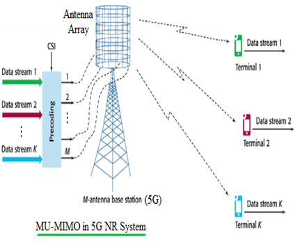

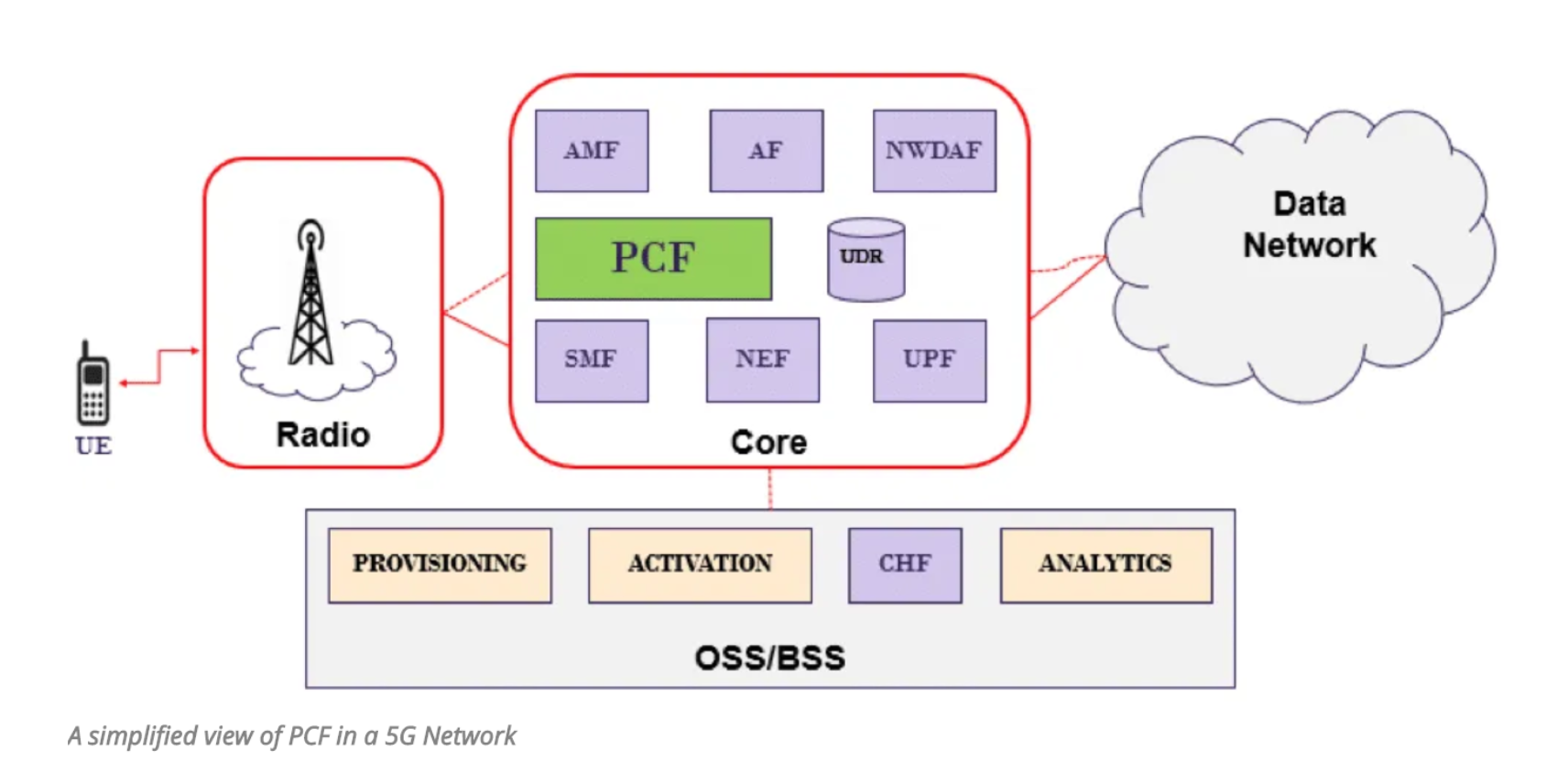

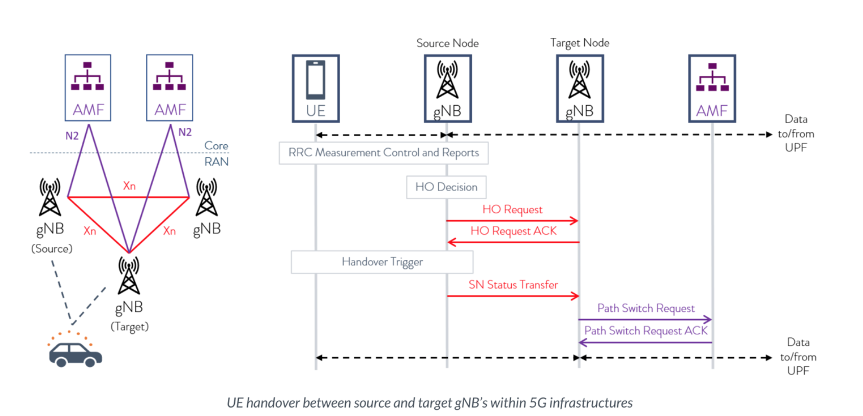

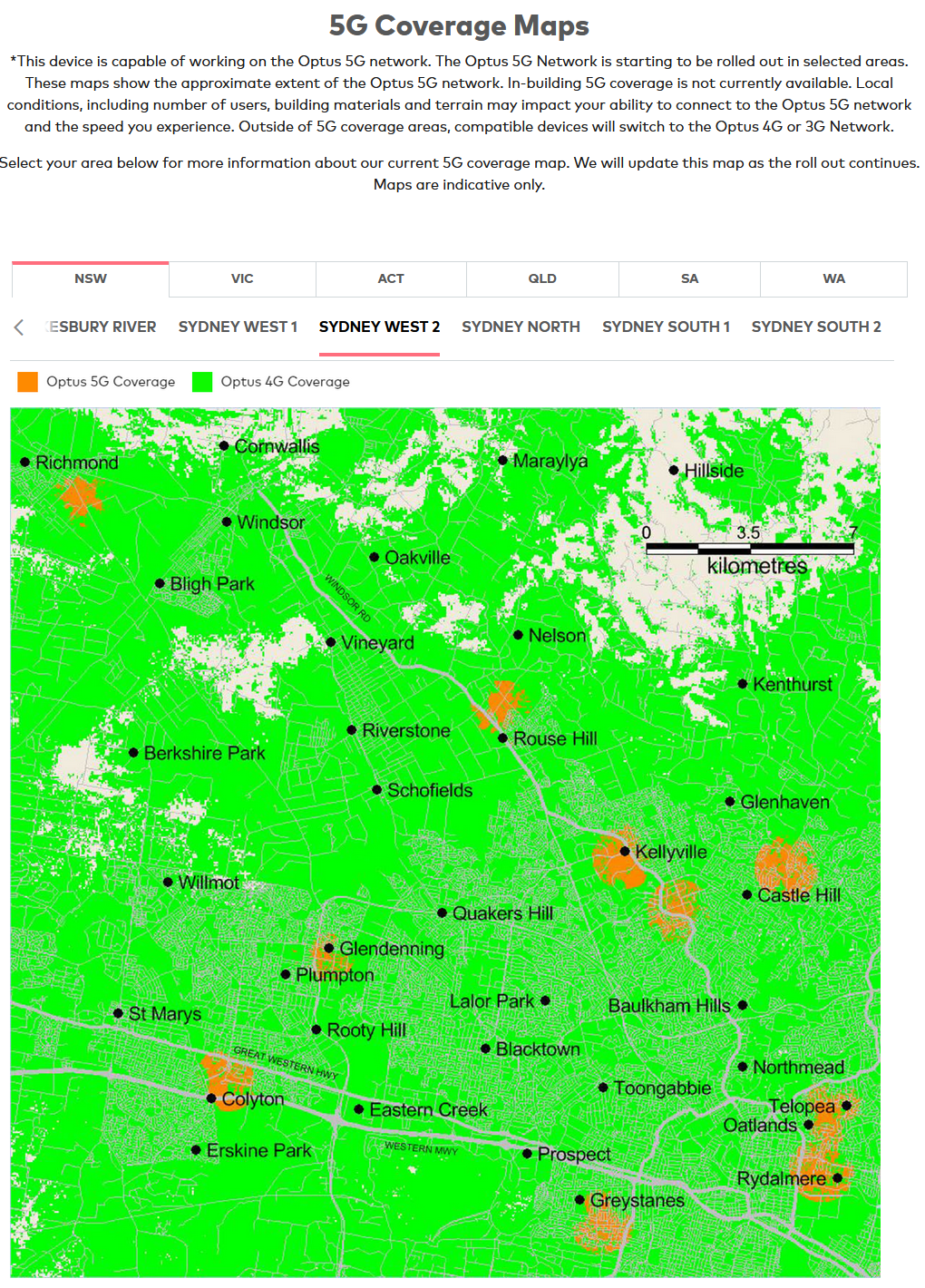


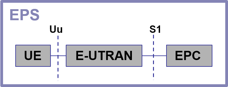


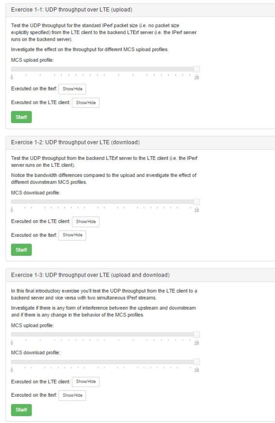

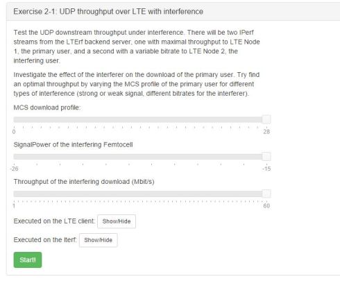

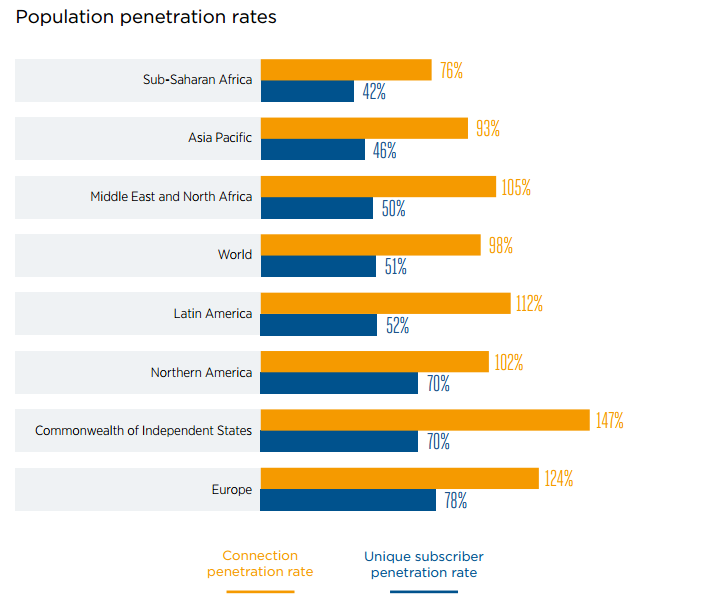
